Lighting / Fixtures
Installation Guide for Hinkley Foundry Stem Hung Fixtures
A comprehensive installation and wiring guide for Hinkley Foundry series stem-hung fixtures. Includes step-by-step assembly, shade attachment, and electrical connection instructions.
Table of contents
Quick Guide from the Manual
This document provides installation instructions for the Hinkley Foundry series stem-hung fixtures. Before beginning, ensure the power supply is turned off. Determine the required length of the fixture and check if additional stems are needed. The fixture is supplied with two 12-inch stems and one 6-inch stem.
Assembly Instructions
Follow these steps to assemble the fixture:
- Find a clear area to work and unpack the fixture and glass.
- Feed the wires (W) from the socket fitter (1) through the stems (2).
- Slide the free end of the wire through the small hole in the end of the stem.
- Continue adding stems until the desired length is achieved.
- Thread the swivel into the top of the last stem.
- Thread the socket fitter (1) into the end of the stem (2).
Mounting the Fixture
- Slide the end of the swivel stem (S) into the neck (N) of the mounting bracket until it is flush with the back of the bracket (6).
- Tighten the three hex head screws (7) into the neck through the holes in the stem. Ensure the swivel bend is correct.
- Secure the swivel (9) to the swivel stem (S).
- Pass the wires through the center hole of the mounting bracket (6).
- Secure the mounting bracket (6) to the junction box (J).
- Slide the canopy (5), washer (8), and logo plate (4) over the swivel (9) and stem (S).
- Slide the decorative collar (3) over the swivel and stem, then tighten with an Allen key to lock the canopy assembly in place.
Shade Installation
- Remove the knurled shade ring (9) from the socket cover (SC).
- Slide the decorative ring (8) onto the edge of the fitter (1), ensuring the recess in the ring faces the edge of the fitter.
- Place the shade (10) and slip the socket through the center hole.
- While holding the shade in position, thread the shade ring (9) back onto the socket cover and tighten to secure.
Wiring and Grounding
Safety Warning: Turn off the power supply during installation. If new wiring is required, consult a qualified electrician.
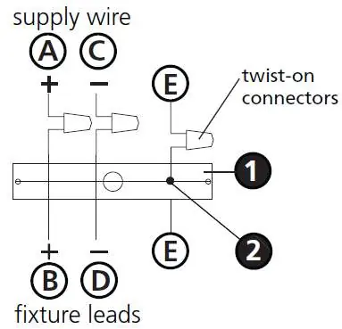
- Positive Wire: Connect the positive supply wire (A) (typically black or smooth side) to the positive fixture lead (B) using a twist-on connector.
- Negative Wire: Connect the negative supply wire (C) (typically white or ribbed side) to the negative fixture lead (D).
- Grounding: Follow the specific grounding instructions for your mounting type (Flush Mount, Chain Hung, or Post-Mount).
- Outdoor Fixtures: Cover the open end of connectors with silicone sealant to form a watertight seal. For wall mounts, use caulk to seal gaps between the mounting plate and the wall.
Important Warnings
- High Wind: Do not use the swivel in high wind areas.
Manufacturer information
Hinkley Lighting
Practical help
Common problems
High wind conditions
Do not use the swivel mechanism in high wind areas.
Water ingress in outdoor installations
Cover the open end of connectors with silicone sealant to form a watertight seal. Use caulk to seal gaps between the mounting plate and the wall.
Before use
- Turn off the power supply at the circuit breaker.
- Clear a workspace for assembly.
- Determine the required fixture length.
- Check if additional stems are needed beyond the included 2-12" and 1-6" stems.
- Verify the swivel bend orientation before mounting.
Images and diagrams
- Drawing 1 (Assembly): Shows the process of feeding wires through stems and attaching the socket fitter.
- Drawing 2 (Assembly): Illustrates the mounting bracket installation and canopy assembly.
- Drawing 1 (Shade): Details the order of the decorative ring, shade, and shade ring.
- Wiring Diagrams: Show specific connections for Flush Mount, Chain Hung, and Post-Mount configurations.
Model compatibility
- Suitable for both indoor and outdoor use (with specific sealing instructions for outdoor).
- Compatible with 3-wire electrical systems for grounding.

Manual page author
David Miller
Documentation analyst
Organizes user manual content into clear summaries, with attention to model details, product context, and everyday usability.