Lighting / Fixtures
Hinkley 83543 Mini Pendant User Manual
Quick guide for installing and adjusting the Hinkley 83543 Mini Pendant. Includes wiring instructions, mounting steps, and shade adjustment details.
Table of contents
Manual images
Click an image to enlargeQuick Guide from the Manual
This document provides installation and adjustment instructions for the Hinkley 83543 Mini Pendant. Before beginning, ensure you have a clear workspace and all necessary tools. Always turn off the power supply at the circuit breaker before starting any electrical work. If you are unfamiliar with electrical wiring, consult a qualified electrician.
Installation Instructions
Follow these steps to mount the fixture:
- Unpack: Carefully remove the fixture from the carton.
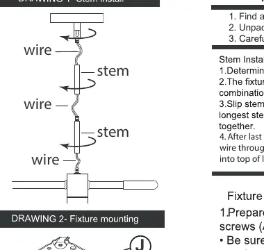
- Stem Assembly: Determine the desired height. Thread the wires through the stems and the swivel. Screw the stems together and attach the swivel to the top of the last stem.
- Fixture Mounting: Prepare the mounting strap (B) by installing screws (A) into the mounting plate (B). Attach the mounting plate to the junction box (J).
- Canopy Attachment: Adjust screws (A) so they extend past the face of the canopy. Once the canopy is flush against the ceiling, secure it using the barrel knobs (D).
Wiring and Grounding
The fixture must be wired according to the specific installation type (Flush Mount, Chain Hung, or Post-Mount). Always use appropriately sized twist-on connectors.
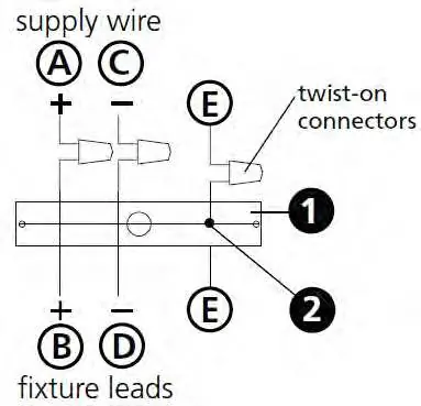
- Positive Wire: Connect the positive supply wire (A) (typically black or smooth) to the positive fixture lead (B).
- Negative Wire: Connect the negative supply wire (C) (typically white or ribbed) to the negative fixture lead (D).
- Grounding: Connect the fixture ground wire (E) (typically copper or green) to the mounting strap (M) using the ground screw (S) or directly to the building's ground system, depending on the installation type.
- Outdoor Installations: Cover the open ends of connectors with silicone sealant to create a watertight seal.
Shade Adjustments
The fixture features adjustable components for directing light:
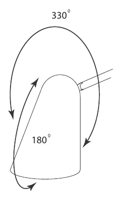
- Rotation: The shades and socket assembly at the end of the arm can rotate 330 degrees.
- Tilt: The assembly can tilt up and down 180 degrees.
Safety Warnings
Read all wiring and grounding instructions (IS 18) before installation. Ensure the power supply is turned off. If new wiring is required, consult a qualified electrician or local authorities to ensure compliance with building codes.
Manufacturer information
Hinkley Lighting
Practical help
Common problems
Water ingress in outdoor installations
Ensure all wire connectors are sealed with silicone sealant and caulk the gap between the mounting plate and the wall.
Fixture not flush with ceiling
Adjust the mounting screws (A) on the mounting strap (B) to ensure they extend the correct distance past the canopy.
Before use
- Turn off the main power supply at the circuit breaker.
- Clear a workspace for assembly.
- Verify all parts are present in the carton.
- Consult a qualified electrician if new wiring is required.
- Ensure you have appropriate twist-on connectors for the wiring.
Specs in practice
- Shade Rotation
- The socket assembly can rotate 330 degrees.
Images and diagrams
- Drawing 1 (Stem install): Illustrates how to thread wires through the stems and attach the swivel.
- Drawing 2 (Fixture mounting): Shows the mounting strap (B) and canopy (C) attachment to the junction box.
- Wiring Diagrams: Provides specific connection paths for Flush Mount, Chain Hung, and Post-Mount configurations.
Model compatibility
- Suitable for indoor and outdoor use (if sealed correctly).
- Requires a 3-wire electrical system for proper grounding.

Manual page author
Michael Turner
Technical manual editor
Reviews PDF manuals for structure, safety notes, and practical product details so readers can find the right information quickly.