Lighting / Fixtures
Assembly and Installation Instructions for Hinkley 1141OL-CL Lantern
Quick guide for assembling and installing the Hinkley 1141OL-CL lantern. Includes steps for glass installation, post mounting, and electrical wiring.
Table of contents
Manual images
Click an image to enlargeQuick Guide
This document provides instructions for the assembly and installation of the Hinkley 1141OL-CL lantern. Always turn off the power supply at the circuit breaker before beginning any installation work. Ensure all electrical connections are made using silicone-filled connectors for outdoor fixtures to maintain a watertight seal.
Glass Installation
Follow these steps to install the glass into the fixture:
- Remove the loop (1) from the top of the fixture, detaching it from the center stem (5).
- Remove the spacer (2) and slide the roof and scroll assembly (3) off the center stem.
- Slide the glass (4) into the fixture, ensuring the small hole at the top of the glass is positioned at the top of the fixture.
- Slide the roof and scroll assembly (3) back onto the center stem (5) and down onto the glass. Ensure the pins (P) at the bottom of the scrolls align with the holes in the top of the uprights (U).
- Replace the spacer (2) and thread the loop (1) back on to complete the assembly.
Post Mounting
To mount the fixture on a post:
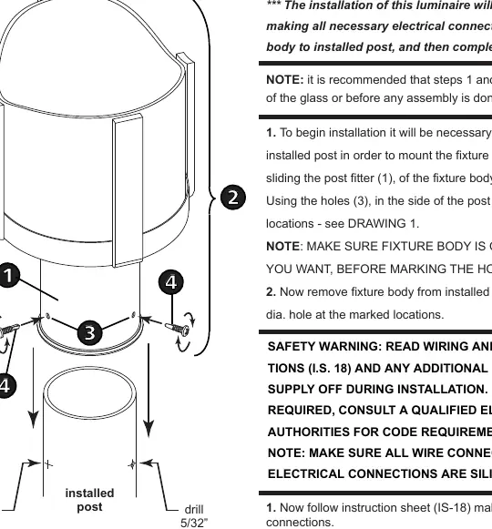
- Slide the post fitter (1) of the fixture body (2) over the installed post.
- Use the holes (3) in the side of the post fitter to mark the mounting hole locations.
- Remove the fixture body and drill 5/32" (4mm) diameter pilot holes at the marked locations.
- Make all necessary electrical connections following the wiring instructions.
- Slide the post fitter (1) back over the installed post, align the holes, and secure the fixture body using the three provided sheet metal screws (4).
Wiring Instructions
Ensure the power is off before proceeding:

- Positive Wire: Connect the positive supply wire (typically black or the smooth, unmarked side of the cord) to the positive fixture lead (B) using an appropriately sized twist-on connector.
- Negative Wire: Connect the negative supply wire (typically white or the ribbed, marked side of the cord) to the negative fixture lead (D).
- Grounding: Connect the fixture ground wire (E) (typically copper or green plastic coated) to the power supply ground using an appropriately sized twist-on connector inside the post.
- Sealing: Cover the open end of all connectors with silicone sealant to form a watertight seal.
Manufacturer information
Hinkley Lighting
Practical help
Common problems
Water entering the fixture
Ensure all wire connectors are silicone-filled and use caulk to seal gaps between the mounting plate and the wall if installing a wall mount fixture.
Fixture not secure on post
Ensure pilot holes are drilled to the correct 5/32" (4mm) diameter and that the three sheet metal screws are fully tightened.
Before use
- Turn off power supply at the main breaker.
- Verify you have a clear workspace.
- Ensure you have a 5/32" (4mm) drill bit.
- Check that all wire connectors are silicone-filled.
- Verify the fixture body orientation before marking holes.
Specs in practice
- Positive Wire
- Typically black or the smooth, unmarked side of the two-conductor cord.
- Negative Wire
- Typically white or the ribbed, marked side of the two-conductor cord.
Images and diagrams
- Drawing 1 (Page 1): Illustrates the glass installation sequence and component identification.
- Drawing 1 (Page 2): Illustrates the post mounting process, including marking and drilling hole locations.
- Drawings 1-3 (Page 3): Wiring diagrams for Flush Mount, Chain Hung, and Post-Mount configurations.
Model compatibility
- Designed for post-top or pier mount installation.
- Requires 3-wire electrical system for proper grounding.

Manual page author
Michael Turner
Technical manual editor
Reviews PDF manuals for structure, safety notes, and practical product details so readers can find the right information quickly.