Automotive / Performance Kits
Installation Manual for HKS Bolt On Turbo Pro Kit GTIII-RS 11001-KT001
Professional installation guide for the HKS Bolt On Turbo Pro Kit GTIII-RS (11001-KT001) designed for Toyota 86 and Subaru BRZ. Includes detailed steps for factory part removal, necessary modifications, turbocharger assembly, and technical...
Table of contents
Manual images
Click an image to enlargeQuick Guide for Installation
This kit is designed for the Toyota 86 (ZN6) and Subaru BRZ (ZC6) with the FA20 engine. Installation must be performed by a professional. The process requires significant modification of factory parts, including cutting the radiator support, reinforcement, and fan shroud. Proper engine management tuning is mandatory to avoid engine damage. Boost pressure is factory-set to 80-90 kPa.
Removal of Factory Parts
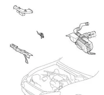
Before beginning, disconnect the negative battery cable and drain the engine oil and coolant. Remove the following factory components:
- Engine under cover
- Side-mounted turn signals
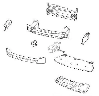
- Front bumper and energy absorber
- Radiator cover plate, horn, and front bumper bracket
- Washer tank and reinforcement
- Air cleaner case, duct, and radiator support
- Fan shroud, exhaust manifold, and oil pan
Modification of Factory Parts
Several factory parts require modification to ensure clearance for the turbo kit:
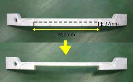
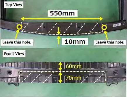
- Reinforcement: Cut the shaded portions as specified to avoid contact with the intercooler.
- Front Bumper Energy Absorber: Cut along the rib on the back.
- Radiator Support: Cut to avoid contact with intercooler piping.
- Fan Shroud: Trim to clear air cleaner and piping.
- Oil Pan: Drill a 17mm hole for the oil return pipe.
Installation Procedures
Follow these steps in order:
- Oil Inlet Parts: Install fittings to the engine block and route the oil inlet hose.
- Turbocharger Bracket: Install the bracket assembly using the provided spacers and bolts.
- Exhaust Manifold: Install the manifold with insulators and the extension bracket.
- Turbocharger Assembly: Attach the oil outlet pipe and stud bolts to the turbocharger.
- Turbocharger and Oil Return Hose: Install the turbocharger to the manifold and connect the oil return hose.
- Extension Pipe: Install the extension pipe with insulators and sensors.
- Accessory Parts: Connect water lines and secure hoses.
- Air Cleaner and Suction Pipe: Install brackets and connect the air cleaner assembly.
- Intercooler and Piping: Mount the intercooler and connect all piping using provided silicone hoses and clamps.
Reinstallation of Factory Parts
Reinstall the front bumper, energy absorber, and engine under cover. Affix sponge sheets and insulator sheets as needed to prevent contact between parts. Reconnect the battery and refill engine oil and coolant.
Technical Information
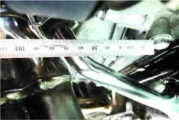
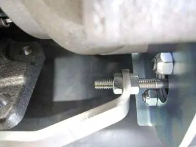
The boost pressure actuator is set to approximately 89 kPa (0.9 kgf/cm²). To increase boost pressure beyond the initial setting, a boost controller (e.g., HKS EVC) is required. Do not adjust boost pressure using the actuator rod beyond the recommended 3mm limit, as this may damage internal parts.
Manufacturer information
HKS Co., Ltd.
Practical help
Common problems
Boost pressure too high or engine power exceeds limits
Upgrade injectors and fuel pump; use a boost controller for adjustments; ensure catalytic converter is used if engine parts are stock.
Interference between pipes and factory parts
Ensure all modifications (cutting reinforcement, radiator support) are performed exactly as specified in the manual.
Oil leakage
Ensure proper installation of oil return pipe and use liquid gasket 1217G on the oil pan; do not use seal tape on oil lines.
Before use
- Verify all parts from the parts list are present.
- Ensure access to a factory service manual.
- Drain engine oil and coolant.
- Confirm vehicle compatibility (Toyota 86/Subaru BRZ FA20).
- Ensure professional tools and equipment are available.
Specs in practice
- Boost Pressure
- Factory set to 80-90 kPa (approx. 0.9 kgf/cm²).
- Oil Viscosity
- Use oil with 40 or higher viscosity at high temperatures.
Images and diagrams
- Reinforcement cutting diagrams show specific dimensions (550mm, 60mm, 70mm) for clearance.
- Oil return pipe diagrams indicate required clearance (15mm from manifold, 20mm from V-belt).
- Actuator adjustment diagram shows the nut and plate position for reducing boost.
Model compatibility
- Designed for Toyota 86 (DBA-ZN6, 4BA-ZN6) and Subaru BRZ (DBA-ZC6, 4BA-ZC6).
- Requires engine management device resetting.
- Upgrading injectors and fuel pump is required.

Manual page author
David Miller
Documentation analyst
Organizes user manual content into clear summaries, with attention to model details, product context, and everyday usability.