Automotive / Performance Kits
HKS Intercooler Kit 13001-AM007 Installation Manual
Comprehensive installation guide for the HKS Intercooler Kit (13001-AM007) designed for the Mitsubishi Lancer Evolution X. Includes detailed modification requirements, step-by-step assembly instructions, and post-installation power...
Table of contents
Manual images
Click an image to enlargeImportant Information Before You Begin
This installation manual is intended for the HKS Intercooler Kit (13001-AM007) for the Mitsubishi Lancer Evolution X (CBA-CZ4A, 4B11 engine, 2007/10 onwards). This installation requires familiarity with automotive systems and basic service procedures. Always have a factory repair manual on hand for safety and reference.
Required Items:
- Power Steering Fluid (Mitsubishi ATF II)
- Paint (Body Color or Black) for touching up cut portions
- Standard automotive tools
Important Advice: For optimal performance, use with factory piping or the HKS Piping Kit (P/N 13002-AM003). Using non-HKS piping may result in fitment issues.
Necessary Modifications
Installation requires several modifications to factory parts. Ensure you have the necessary tools to cut, disassemble, and relocate components as detailed in the manual:
- Power steering cooler pipe: Modify pipe shape and bracket.
- AC condenser: Remove stopper/cut stopper and add gaps in the bracket.
- AC pipe: Modify pipe shape.
- Headlight support upper panel: Cut bracket.
- Reinforcement: Disassemble rivets, cut sections, and add gaps to the power steering pipe bracket and reinforcement.
- Front bumper air guide duct: Cut off protruding sections.
- Intercooler bracket (RH): Cut bracket.
- Front bumper air guide: Cut plastic.
- Headlight support cover: Remove ribbed section.
Removal of Factory Parts
- Disconnect the negative terminal cable of the vehicle’s battery.
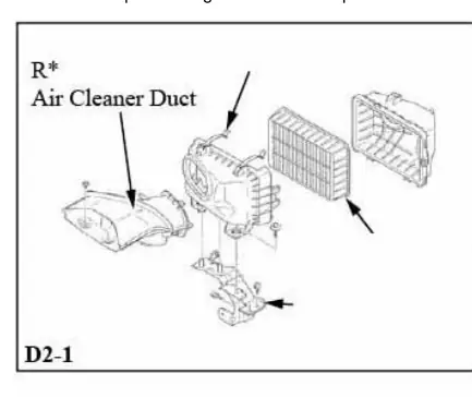
- Remove the air cleaner duct (this part will be reused).
- Remove the engine room under covers (front A, front B, and center).
- Remove the headlight support cover, front bumper assembly, front bumper air guide center duct, and front bumper reinforcement.
- Remove the intercooler pipe, hoses, and intercooler core assembly. Keep bolts and hose clamps for reuse.
Installation of Kit Parts
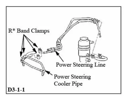
Relocating the Power Steering Cooler Pipe
Prepare a drainage tub for power steering fluid. Bend the cooler pipe to avoid contact with the front bumper assembly and AC condenser. Use the provided Power Steering Pipe Bracket to mount the pipe vertically.
Relocating the AC Condenser
Relocate the AC condenser approximately 5mm to the vehicle's left by cutting the right-side stoppers. Use tie wraps to secure the condenser in the newly created gaps.
Intercooler Core Assembly Installation
Install Intercooler Bracket No.2. Pre-tighten the lower bolt of the Intercooler Core Assembly to check for contact points. Bend the AC pipe (thin) towards the rear of the vehicle to prevent contact with the intercooler tank bottom. Caution: Do not apply excessive force near flanged sections of the pipe to prevent leaks.
Procedures After Installation
After installing the kit, you must bleed the power steering system:
- Reconnect the negative battery terminal.
- Jack up the front of the vehicle and support it on jack stands.
- Disconnect the crank angle sensor.
- Refill power steering fluid to the minimum level.
- Crank the engine intermittently (15-20 seconds) and turn the steering wheel right and left until it locks (repeat 5-6 times).
- Reconnect the crank angle sensor, start the engine, and let it idle.
- Turn the steering wheel until the reservoir stops bubbling.
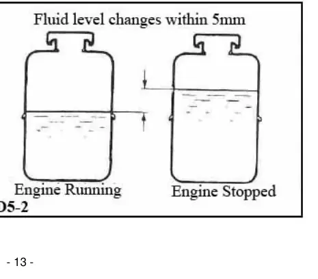
- Verify fluid levels are stable and not cloudy.
Manufacturer information
HKS Co., Ltd.
Practical help
Common problems
Power steering fluid leakage or noise
Ensure the bleeding process is complete. If fluid levels fluctuate more than 5mm after turning the engine on/off, repeat the bleeding process.
Fitment issues with piping
Use the factory piping or the HKS Piping Kit (P/N 13002-AM003). Non-HKS piping may not fit correctly.
Intercooler tank contact with AC pipe
Bend the AC pipe (section A) towards the rear of the vehicle. Ensure a large radius bend to prevent cracks.
Before use
- Disconnect the negative battery terminal.
- Prepare a drainage tub for power steering fluid.
- Obtain Mitsubishi ATF II power steering fluid.
- Have paint ready to touch up cut metal/plastic parts.
- Verify you have a factory repair manual for reference.
Specs in practice
- AC Condenser Relocation
- Move approximately 5mm to the vehicle's left.
- Intercooler Pipe Clearance
- Maintain at least 1cm of clearance between pipes.
- Power Steering Fluid Fluctuation
- Should not exceed 5mm after turning the engine on and off.
Images and diagrams
- D3-1-1 to D3-1-5: Power steering cooler pipe relocation and bracket mounting.
- D3-2-1 to D3-2-4: AC condenser bracket modification and relocation.
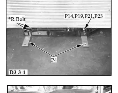
- D3-3-1 to D3-3-3: Intercooler core installation and clearance adjustments.
- D5-1 to D5-2: Post-installation power steering fluid bleeding and level verification.
Model compatibility
- Vehicle: Mitsubishi Lancer Evolution X / CBA-CZ4A (USDM).
- Year: 2007/10 onwards.

Manual page author
Michael Turner
Technical manual editor
Reviews PDF manuals for structure, safety notes, and practical product details so readers can find the right information quickly.