Toys / RC Components
Hobbywing XERUN BANDIT G4R Sensored Brushless Motor
Quick guide for the Hobbywing XERUN BANDIT G4R sensored brushless motor. Includes installation, wiring, timing adjustment, FDR recommendations, and maintenance steps.
Table of contents
Manual images
Click an image to enlargeQuick guide from the manual
The Hobbywing XERUN BANDIT G4R is a high-performance sensored brushless motor designed for 1/10 outlaw stock racing. This guide covers essential setup, wiring, timing adjustments, and maintenance procedures to ensure optimal performance and longevity.
Cautions and Safety
- Wiring: Carefully check the wire sequence between the ESC and the motor to avoid incorrect connections.
- Soldering: Limit soldering time to within 5 seconds using a soldering iron of at least 60W to prevent overheating damage.
- Temperature: Stop usage if the motor exceeds 100°C (212°F). High temperatures can weaken the rotor and damage the motor.
- No-Load Operation: Never apply full throttle without a pinion gear mounted, as high RPMs can damage the motor.
- Liquids: Keep the motor away from water, oil, fuel, or other electro-conductive liquids.
Installation and Connection
To install the motor, use M3 mounting screws. Ensure the mounting holes are 4mm in depth and verify the screw length is appropriate to avoid damaging the motor.
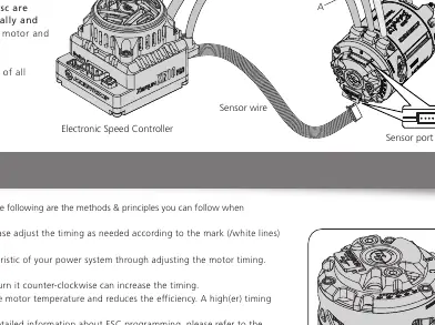
Wiring to ESC: Connect the motor wires to the ESC by matching the marked phases (A-A, B-B, C-C). Ensure the sensor cable is also connected to both the motor and the ESC. Always inspect the installation and connection order before powering on the ESC.
Timing Adjustment
The BANDIT G4R features an adjustable end-bell timing range of 20-60 degrees (default is 43 degrees).
- To adjust, loosen the screw on the rear end plate.
- Turn the rear end plate clockwise to reduce timing or counter-clockwise to increase timing.
- Increasing timing boosts motor speed (RPM) but also increases temperature and reduces efficiency.
- After adjustment, ensure the motor does not overheat during a full battery run. If it gets too hot, reduce the timing or increase the Final Drive Ratio (FDR).
Recommended FDR
The Final Drive Ratio (FDR) should be adjusted based on track conditions, traction, tires, and vehicle weight. Start with the recommended FDR values provided in the manual for Blinky mode and adjust based on test results. If no specific recommendation applies, start with a larger FDR and adjust gradually.
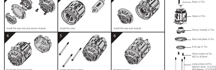
Assembly and Dis-assembly
The motor is designed for easy maintenance. Periodically check the bearings and clean the motor. To disassemble, reverse the assembly sequence: remove the end cap, rear end plate, sensor module, stator, rotor, and front end plate. Ensure all components are reinstalled correctly during assembly.
Specifications
- Models: 13.5T-OBL, 13.5T-TORQUE, 17.5T
- KV (No-load): 3800KV (13.5T-OBL), 3200KV (13.5T-TORQUE), 2500KV (17.5T)
- Poles: 2
- Applications: 1/10 Outlaw STOCK Racing
Manufacturer information
Hobbywing
Practical help
Common problems
Motor overheating
Check if the timing is too high, the FDR is too low, or if the motor is being pushed beyond its limits. Let it cool down before further use.
Motor not running normally
Verify the wire sequence (A-A, B-B, C-C) between the ESC and motor. Ensure the sensor cable is properly connected.
Soldering damage
Ensure soldering time is kept under 5 seconds using a 60W+ iron to prevent heat damage to the motor tabs.
Before use
- Check wire sequence between ESC and motor
- Ensure all components are well insulated
- Verify gearing and overall setup
- Check motor temperature during initial runs
- Ensure ESC is properly programmed
Specs in practice
- FDR (Final Drive Ratio)
- The ratio between pinion gear and tires; crucial for tuning performance and temperature.
Images and diagrams
- Wiring diagram shows the correct connection of phases A, B, and C between the motor and ESC, plus the sensor wire connection.
- Assembly diagram illustrates the sequence for disassembling and reassembling the motor components.
Model compatibility
- Designed specifically for 1/10 Outlaw Stock Racing.
- Requires ESC with compatible sensor port.

Manual page author
David Miller
Documentation analyst
Organizes user manual content into clear summaries, with attention to model details, product context, and everyday usability.