Toys / RC Components
User Manual for Hobbywing Xerun V10 G4R Sensored Brushless Motor
Quick guide for the Hobbywing Xerun V10 G4R sensored brushless motor. Includes installation, wiring, timing adjustment, FDR recommendations, and maintenance steps.
Table of contents
Manual images
Click an image to enlargeQuick guide from the manual
The Hobbywing Xerun V10 G4R is a high-performance sensored brushless motor designed for 1/10 scale racing. Key operational points include:
- Wiring: Ensure phases A, B, and C are connected to the corresponding ESC terminals.
- Timing: Adjustable between 20-60 degrees (default is 43°). Clockwise reduces timing; counter-clockwise increases it.
- Overheating: If the motor runs too hot, reduce timing or increase the Final Drive Ratio (FDR) by using a smaller pinion gear.
- Safety: Never run the motor at full throttle without a pinion gear (no-load) to avoid damage.
Installation and Connection
Follow these steps to install the motor:
- Mounting: Use M3 screws. Ensure the mounting holes are 4mm deep; verify screw length to avoid damaging the motor internals.
- Wiring: Connect the motor wires to the ESC phases (A-A, B-B, C-C). Incorrect wiring will prevent the motor from running and may damage the ESC.
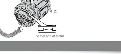
- Sensor Cable: Connect the sensor cable between the motor and the ESC.
- Inspection: Check all connections and installation before powering on the ESC.
Timing Adjustment
The motor timing can be adjusted to change power characteristics:
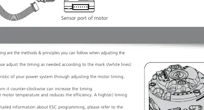
- Loosen the screw on the rear end plate.
- Rotate the rear end plate according to the white line marks.
- Fasten the screw after adjustment.
- Note: Increasing timing increases RPM but also raises motor temperature and reduces efficiency.
Recommended FDR
The Final Drive Ratio (FDR) should be adjusted based on track conditions. Start with the recommended values for Blinky mode:
- 13.5T: 4.7 (Small Track), 4.0 (Big Track), 7.6 (2WD Off-road), 8.3 (4WD Off-road).
- 17.5T: 4.0 (Small Track), 3.5 (Big Track), 6.6 (2WD Off-road), 7.5 (4WD Off-road).
If no recommended FDR is applicable, start with a larger FDR (more teeth on the spur gear or fewer on the pinion) and adjust gradually.
Assembly and Dis-assembly
The motor is designed for easy maintenance. To disassemble, reverse the assembly sequence:
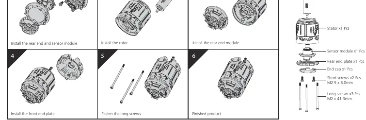
- Install the rear end and sensor module.
- Install the rear end module.
- Install the rotor.
- Install the front end plate.
- Fasten the long screws.
Regularly check the bearings and clean the motor to maintain performance.
Manufacturer information
Hobbywing
Practical help
Common problems
Motor overheating
Reduce timing or increase FDR (use fewer pinion teeth or more spur gear teeth). Check temperature after running a full LiPo pack.
Motor not running or ESC damaged
Verify wiring order (A-A, B-B, C-C). Ensure sensor cable is connected.
High RPM damage
Never apply full throttle without a pinion gear mounted (no-load condition).
Before use
- Ensure all wires and joints are well insulated.
- Check that mounting screws are not longer than 4mm to avoid internal damage.
- Verify ESC is programmed correctly before setting motor timing.
- Ensure the motor casing does not exceed 100°C/212°F.
Images and diagrams
- Wiring: Connect A, B, and C phases to the corresponding ESC terminals.
- Timing Adjustment: Turn rear end plate clockwise to reduce timing, counter-clockwise to increase.
Model compatibility
- ROAR version: Use for ROAR rules (lower temperature rise).
- Standard version: Use for EFRA rules.

Manual page author
Michael Turner
Technical manual editor
Reviews PDF manuals for structure, safety notes, and practical product details so readers can find the right information quickly.