Toys / RC Components
User Manual for Hobbywing Skywalker 130A HV OPTO V2 and 160A HV OPTO V2 Electronic Speed Controller
Quick guide for the Hobbywing Skywalker 130A HV OPTO V2 and 160A HV OPTO V2 Electronic Speed Controller. Includes wiring diagrams, calibration steps, programming instructions, and troubleshooting.
Table of contents
Manual images
Click an image to enlargeQuick guide from the manual
This document provides essential instructions for the Hobbywing Skywalker 130A HV OPTO V2 and 160A HV OPTO V2 Electronic Speed Controllers (ESC). Before operating, ensure all wires are properly insulated and the input voltage is within the specified range. Always ensure the throttle is at the lowest position before connecting the battery to the ESC.
Product Overview
The Skywalker HV OPTO V2 series features a 32-bit ARM microprocessor for high performance. These ESCs are designed for brushless motors and include multiple protection features such as start-up protection, thermal protection, and throttle signal loss protection. Note that these models are OPTO, meaning they do not include a BEC (Battery Eliminator Circuit) and require a separate power source for the receiver.
Connections
Proper wiring is critical for safe operation:
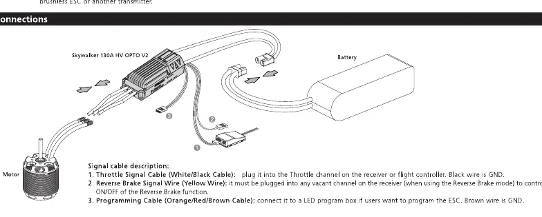
- Motor: Connect the three motor wires to the ESC output wires.
- Battery: Connect the battery to the ESC input wires.
- Receiver: Plug the throttle cable into the throttle channel on your receiver.
- Programming: Use the programming port to connect an optional LED program box.
ESC and Radio Calibration
To ensure the ESC works correctly with your transmitter, perform the calibration process:
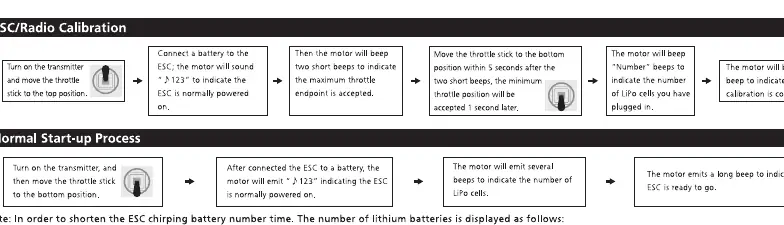
- Turn on the transmitter and move the throttle stick to the top position.
- Connect the battery to the ESC.
- The motor will emit two beeps to indicate the maximum throttle endpoint is accepted.
- Move the throttle stick to the bottom position within 5 seconds.
- The motor will emit beeps to indicate the number of LiPo cells.
- The motor will emit a long beep to indicate the calibration is complete.
Programming
The ESC can be programmed using an LED Program Box or via the transmitter:
- LED Program Box: Connect the ESC to the program box. Select items and values, then press OK to save.
- Transmitter: Enter the programming mode by moving the throttle stick to the top position, connecting the battery, and waiting for the motor to beep. Follow the beep sequences to select parameters and values as outlined in the parameter table.
Multiple Protections
The ESC includes several safety features:
- Start-up Protection: If the motor fails to start normally, the ESC will restart.
- Thermal Protection: If the temperature exceeds 120 degrees Celsius, the output power will be reduced to 60%.
- Throttle Signal Loss Protection: The ESC will cut off output if the signal is lost for more than 0.25 seconds.
- Low Voltage Protection: The ESC will reduce output power if the voltage drops below the threshold.
Troubleshooting
If you encounter issues, check the following:
- ESC doesn't work after power-on: Check if the input voltage is within the operating range.
- ESC doesn't work after power-on (beeps): Check if the receiver is connected properly.
- ESC doesn't work after throttle calibration: Re-calibrate the throttle range.
- Output reduced to 50%: The ESC has triggered thermal protection; allow it to cool down or improve ventilation.
Manufacturer information
Hobbywing
Practical help
Common problems
ESC does not work after power-on
Check if the input voltage is within the operating range.
ESC does not work after power-on (beeps)
Check if the receiver is connected properly and the signal cable is intact.
ESC does not work after throttle calibration
Re-calibrate the throttle range by following the calibration steps.
Output power reduced to 50%
Thermal protection has been triggered. Improve cooling or ventilation.
Before use
- Ensure all wires are insulated to prevent short circuits.
- Verify input voltage is within the specified range (6-14S LiPo).
- Ensure the throttle stick is at the lowest position before connecting the battery.
- Verify the receiver is powered separately (OPTO ESC has no BEC).
Images and diagrams
- Wiring diagram: Shows connections between the motor, ESC, battery, and receiver.
- Programming flow: Illustrates the sequence of beeps and stick movements to enter and navigate the programming menu.
Model compatibility
- Requires separate receiver power source (no BEC).
- Compatible with standard transmitters (1100us to 1940us throttle range).

Manual page author
Emily Carter
User documentation editor
Prepares concise manual descriptions and highlights the most useful setup, operation, and maintenance information for readers.