Home / Security
Installation Guide for Honeywell OmniSmart Reader 20/20K/40/40K
Comprehensive installation and wiring guide for Honeywell OmniSmart Reader models 20, 20K, 40, and 40K. Includes step-by-step mounting instructions, wiring diagrams, technical specifications, and regulatory compliance information.
Quick answers from the manual
Quick answer
- To install the Honeywell OmniSmart Reader, mount the backplate to a flat surface, wire the reader according to the color-coded table provided in the manual, secure the reader to the plate with the provided screw, and test with a credential. p. 1
Key actions
- Mounting the plate p. 1
- Wiring the reader p. 1
- Configuring facility code p. 1
First start
- Power on and test p. 1
Problems and fixes
Reader LED displays solid red
Power-cycle the reader and retry entering the facility code.
p. 1Technical specifications
| Parameter | Value | Meaning | Pages |
|---|---|---|---|
| Input Voltage | 12V DC | Required power supply voltage. | p. 2 |
| Operating Temperature | -30° F to 150° F (-35° C to 66° C) | Allowed environmental temperature range. | p. 2 |
Where to find it in the PDF
- Installation and Wiring p. 1
- Specifications and Regulatory p. 2
Table of contents
Quick Guide from the Manual
This document provides installation instructions for the Honeywell OmniSmart Reader series (20, 20K, 40, 40K). The installation process involves mounting the backplate, wiring the reader according to the specific interface (Pigtail or Terminal), securing the reader, and performing a power-on test. Ensure you use a UL294 listed power supply and follow all local electrical codes.
Mounting the Reader
The reader is installed using a mounting plate. Ensure the surface is flat and stable. Use the supplied screws to attach the mounting plate to the wall or junction box. Be aware of electrostatic sensitive devices during handling.
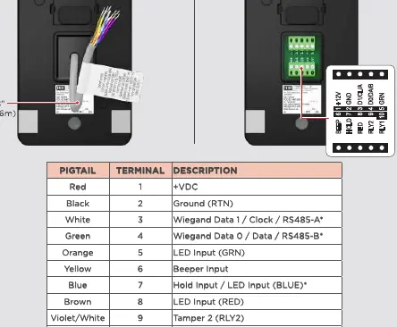
Wiring the Reader
The reader supports different wiring configurations. Incorrect wiring may permanently damage the device. Refer to the wiring table provided in the manual for specific color codes (Red, Black, White, Green, Orange, Yellow, Blue, Brown, Violet/White, Violet, Bare). Note that previous OmniCLASS readers had reversed RS-485 wiring; ensure proper connections for the OmniSmart reader. For OSDP cable lengths exceeding 200 ft (61 m) or in cases of EMF interference, install a 120 ohm resistor across RS-485 termination ends.
Securing the Reader
Once wired, hook the top of the reader onto the mounting plate. Align the bottom of the reader with the mounting plate and secure it using the provided security or standard screw.
Testing
After installation, power the reader. The reader will beep and the LED will flash. Test the reader with a valid credential to ensure proper functionality.
Specifications
The readers operate on 12V DC. Current consumption varies by model (20, 20K, 40, 40K) and activity (Standby vs. Peak). Operating temperature ranges from -30° F to 150° F (-35° C to 66° C). Cable length limits depend on the communication protocol (Wiegand or RS-485).
Regulatory and Safety
The device complies with FCC Part 15 rules and Industry Canada license-exempt RSS standards. It is intended for use with listed (UL294) control equipment. Ensure installation is in accordance with NFPA70 (NEC) and local codes.
Manufacturer information
Honeywell International Inc.
Practical help
Common problems
Reader LED displays solid red after entering facility code
Power-cycle the reader and retry entering the facility code within five seconds of power-up.
Two short beeps after entering a PIN
The reader facility code is not configured. Power-cycle the reader and retry.
Wiring damage
Ensure wiring matches the provided table exactly; incorrect wiring may permanently damage the reader.
Before use
- Verify the power supply is a Listed Access Control / Burglary power-limited supply.
- Ensure the mounting surface is flat and stable.
- Check if you are using Pigtail or Terminal wiring configuration.
- Confirm cable type meets requirements (Wiegand vs RS-485 twisted pair).
- Have the facility code ready for keypad configuration.
Specs in practice
- Input Voltage
- 12V DC required for all models.
- Wiegand Cable Length
- Max 500 ft (152 m) with 18 AWG, or 300 ft (91 m) with 20 AWG.
- RS-485 Cable Length
- Max bus length 4,000 ft (1,219 m) with 24 AWG.
Images and diagrams
- Wiring Table: Maps wire colors to specific functions (e.g., Red to +VDC, Black to Ground).
- Mounting Plate: Shows screw placement for wall or junction box installation.
- Securing Mechanism: Illustrates hooking the reader onto the plate and fastening the security screw.
Model compatibility
- Compatible with HID Mobile Access version 3.0.0 and later.
- Supports Wiegand, OSDP, and Bluetooth communications.
- Previous OmniCLASS readers had reversed RS-485 wiring; do not use old wiring schemes.

Manual page author
David Miller
Documentation analyst
Organizes user manual content into clear summaries, with attention to model details, product context, and everyday usability.