HVAC / Air Conditioners
Installation Guide for Hotpoint 1H09HN2DAA Ductless Single Zone Air Conditioner
Comprehensive installation guide for the Hotpoint 1H09HN2DAA ductless single zone air conditioner. Includes safety warnings, mounting instructions, electrical wiring, refrigerant charging, and leak testing procedures.
Quick answers from the manual
Quick answer
- This manual provides installation instructions for Hotpoint Ductless Single Zone systems using R32 refrigerant. Installation must be performed by a licensed HVAC technician. p. 1, 11
Key actions
- Install indoor unit mounting plate p. 15
- Perform leak test p. 19
- Evacuate system p. 20
First start
- Ensure proper grounding and wiring connections before powering on. p. 2, 16
Problems and fixes
E7 error code
Check for improper wire size, use of solid core wire, midline splicing, or poor terminal connections.
p. 18Technical specifications
| Parameter | Value | Meaning | Pages |
|---|---|---|---|
| Refrigerant | R32 | Flammable refrigerant type | p. 11 |
Where to find it in the PDF
- Safety Information p. 2, 3, 4
- Installation Instructions p. 11, 15, 16, 18
- Warranty p. 23, 24
Table of contents
Manual images
Click an image to enlargeQuick guide from the manual
This document provides installation instructions for the Hotpoint Ductless Single Zone air conditioner system. Installation must be performed by a licensed HVAC technician. The system uses R32 refrigerant, which is flammable and requires specific handling, tools, and safety standards. Do not use equipment certified only for R22 or R410A.
Safety Information
Warning: For your safety, follow all instructions to minimize the risk of fire, electric shock, or personal injury.
- Use only copper wiring rated for the amperage listed on the rating plate.
- Do not use extension cords.
- Ensure the unit is properly grounded.
- Disconnect all power supplies before servicing.
- Do not store or use combustible materials, gasoline, or other flammable vapors near the appliance.
- Any service requiring entry into the refrigerant sealed system must be performed by a technician with Class II or Universal certification.
Installation
Indoor Unit
Select a location with no obstacles in front, at least 4 inches of clearance from the ceiling, and 3 feet away from other electrical appliances. Use a stud finder to locate studs for mounting the plate. Ensure the wall is strong enough to support the unit's weight and vibration.
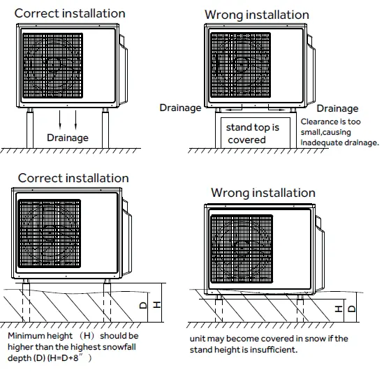
Outdoor Unit
Choose a level, solid location that will not amplify noise. Ensure sufficient space for air inlet and outlet. Install power/communication wiring at least 10 feet away from radio or television sets to prevent interference. The unit cannot be hung from a ceiling or stacked.
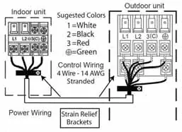
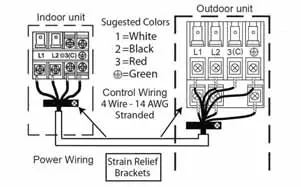
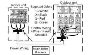
Wiring
Use 14/4 AWG SOOW copper stranded cable. Ensure wiring connections match wire-for-wire between indoor and outdoor units. Secure cables under strain relief brackets. Failure to follow wiring guidelines can result in control board damage and communication issues (E7 error code).
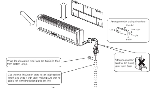
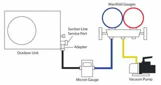
Piping and Charging
Use the R32 flaring tool for copper linesets. Torque fittings according to specifications (1/4" at 18 N.m, 3/8" at 42 N.m, 1/2" at 55 N.m, 5/8" at 60 N.m). Perform a leak test using dry nitrogen up to 500 psig. Evacuate the system to at least 350 microns. Charge with liquid refrigerant only using a digital scale.
Final Check
Verify no gas leaks, proper insulation, secure wiring, correct condensate drainage, and accurate temperature drops/rises during a test run.
Practical help
Common problems
E7 error code
Check for improper wire size, use of solid core wire, midline splicing, or poor terminal connections.
Refrigerant leak
Use soap bubbles or an electronic leak detector; do not use naked flames for detection.
Before use
- Verify all wiring complies with local building codes and NEC.
- Ensure R32 refrigerant handling equipment is available.
- Check for proper grounding of both indoor and outdoor units.
- Confirm installation location is strong enough for unit weight.
- Ensure condensate drainage has a constant downward slope.
- Verify the lineset is properly insulated.
Specs in practice
- R32 Refrigerant
- Flammable refrigerant requiring specialized handling and certification.
- 14/4 AWG Cable
- Required copper stranded cable for power and communication.
- Standard Pipe Length
- 25ft; no extra gas needed up to this length.
Images and diagrams
- Wiring diagram showing connections between indoor and outdoor units.
- Clearance diagrams for indoor and outdoor unit placement.
- Condensate drainage slope requirements.
Model compatibility
- Only connect units labeled with the same refrigerant.
- Requires licensed HVAC technician for installation and service.

Manual page author
David Miller
Documentation analyst
Organizes user manual content into clear summaries, with attention to model details, product context, and everyday usability.