HVAC / Air Conditioners
Service Manual for Hotpoint Single Zone Ductless Split Systems
Comprehensive service manual for Hotpoint Single Zone Ductless Split Systems. Includes technical specifications, component identification, wiring diagrams, service procedures, and detailed troubleshooting flowcharts for error codes.
Quick answers from the manual
Quick answer
- This service manual provides technical specifications, component identification, wiring diagrams, and troubleshooting flowcharts for Hotpoint Single Zone Ductless Split Systems. p. 1, 33
Key actions
- Check wiring for communication errors (E7). p. 7, 40
- Perform resistance checks on sensors. p. 22, 42
First start
- Ensure dedicated power circuit and proper clearance. p. 4
Problems and fixes
E7 Communication Failure
Check terminal 3 wiring for splices or breaks.
p. 40Error codes
| Code | Meaning | Action | Pages |
|---|---|---|---|
| E7 | Communication failure | Check wiring | p. 34 |
| F1 | IPM Overcurrent | Check IPM/Compressor | p. 34, 38 |
Maintenance and reset
- Remove power to the system to reset lock-out conditions. p. 11
Technical specifications
| Parameter | Value | Meaning | Pages |
|---|---|---|---|
| Voltage | 208-230V | Operating voltage | p. 5, 6 |
Where to find it in the PDF
- Specifications p. 5, 6
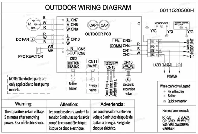
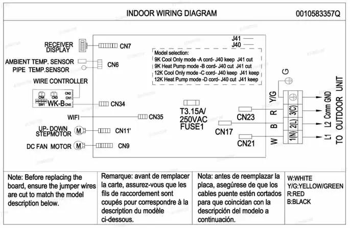
- Wiring Diagrams p. 23, 32
Table of contents
Manual images
Click an image to enlargeImportant Information from the Manual
This service manual is intended for professional technicians. Before troubleshooting or servicing, ensure all installation requirements, including wiring, clearance, and line set specifications, have been met. The system operates on 208/230V power. Miswiring, especially on the communication terminal (3), will cause an E7 error code.
System Overview
The system consists of a wall-mounted indoor unit and an inverter-driven outdoor unit. It uses R32 refrigerant and PVE oil. The system features variable speed operation to match comfort requirements.
Operation Modes
- Cooling Mode: Temperature range 60°F - 86°F. The system adjusts compressor frequency based on the difference between set point and room temperature.
- Heating Mode: Temperature range 60°F - 86°F. Includes cold air proof operation and automatic defrost cycles.
- Dry Mode: Used for dehumidification. Recommended not to exceed 4 hours to prevent condensate overflow.
- Auto Mode: Automatically switches between cooling, heating, and fan modes based on room temperature.
Components
The manual provides detailed identification for both outdoor and indoor units, including PCBs, sensors, and motors. Key components include:
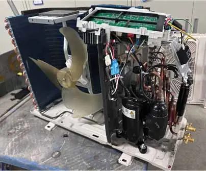
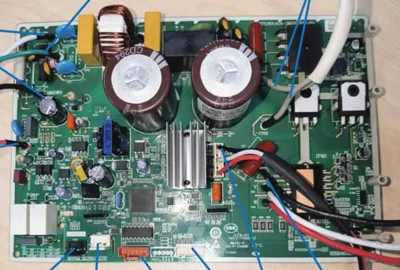
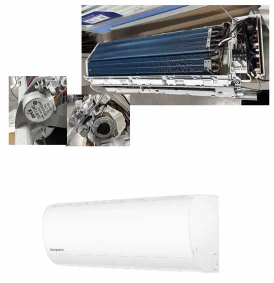
- Outdoor Unit: Compressor, 4-way valve, EEV, fan motor, and control board.
- Indoor Unit: Fan motor, louver motors, display panel, and sensors.
Service Procedures
Technicians should use needle probes to test components to avoid damaging connectors. Procedures include:
- Checking Sensors: Use a k-type temperature probe and ohmmeter to verify resistance against the provided charts.
- Checking Motors: Verify DC voltages at the PCB connectors.
- Checking Compressor Windings: Ensure balanced resistance (within +/- 20%) between U, V, and W terminals.
Troubleshooting
The manual includes extensive flowcharts for diagnosing issues. Common error codes include:
- E7: Communication failure between indoor and outdoor units.
- F1: IPM power module protection.
- F2: Compressor overcurrent.
- E14: Indoor fan motor failure.
Always cycle power to the unit when troubleshooting to reset the system.
Practical help
Common problems
Communication error (E7)
Check wiring between indoor and outdoor units; ensure no splices in terminal 3 wire.
Compressor won't start
Check for over-current protection, IPM faults, or loose wiring.
Fan motor failure
Check DC voltage at plug CN9/CN10; verify motor rotates freely.
Before use
- Verify installation on a solid base.
- Ensure dedicated power circuit.
- Check refrigerant lines for leaks.
- Confirm proper clearance around units.
Images and diagrams
- Wiring diagrams show connections for outdoor PCB, fan, reactor, and terminal block.
- PCB diagrams identify connector locations (CN1-CN16).
Model compatibility
- Models 1HxxHN2CAA1 are Cooling Only.
- Models 1HxxHN2DAA1 are Heat Pump models.

Manual page author
David Miller
Documentation analyst
Organizes user manual content into clear summaries, with attention to model details, product context, and everyday usability.