HVAC / Water Heaters
User Manual for HTW Evolution Electric Water Heater
Quick guide for the HTW Evolution electric water heater series. Includes installation steps, usage instructions, maintenance, troubleshooting, and technical specifications.
Table of contents
Manual images
Click an image to enlargeQuick Guide from the Manual
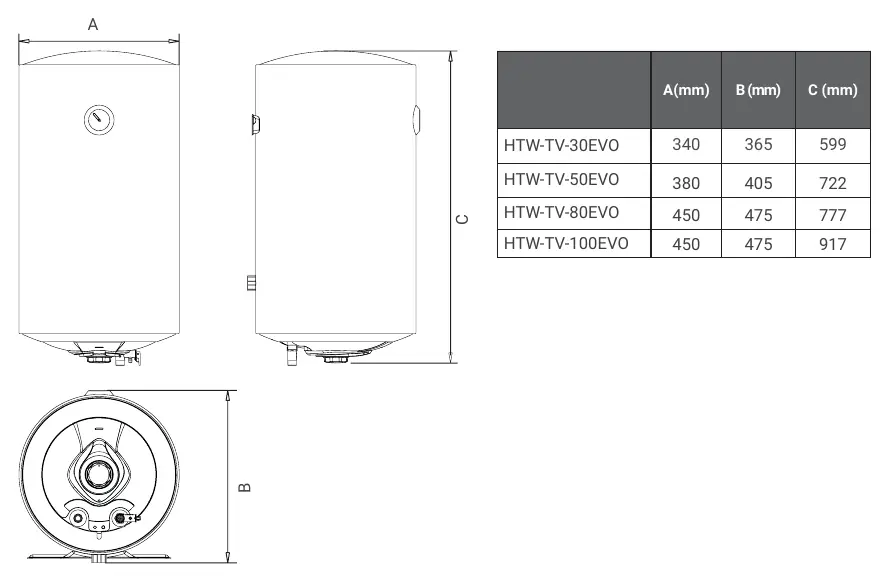
This manual covers the installation, operation, and maintenance of the HTW Evolution electric water heater series (HTW-TV-30EVO, HTW-TV-50EVO, HTW-TV-80EVO, HTW-TV-100EVO). Before using the appliance, ensure it is properly installed, filled with water, and connected to a grounded power supply. Always confirm water temperature before use to avoid scalding.
Parts of the Water Heater
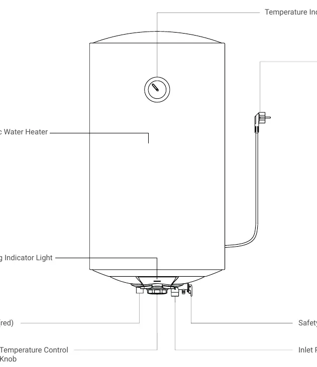
The unit consists of the main heater body, a temperature indicator, a heating indicator light, a temperature control knob, an inlet pipe (blue), an outlet pipe (red), a safety valve, and a power plug.
Installation
Precautions: The wall must support at least four times the total mass of the appliance when filled with water. Install in an indoor, frost-free environment. Use the provided accessories and ensure the power socket is reliably grounded.
Installation Steps:
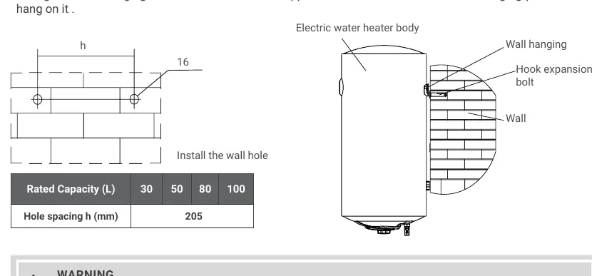
- Determine the installation position and drill two horizontal holes (depth at least 90mm).
- Insert two hook expansion bolts and tighten them with the hooks facing upwards.
- Align the hanging holes on the back of the appliance with the hooks and hang the unit securely.
Tube Connection: The inlet and outlet interface is G1/2. Connect the safety valve to the inlet port with the arrow pointing in the direction of flow. Connect a drain pipe to the safety valve outlet, ensuring it leads to a safe drainage point (e.g., floor drain) and remains unobstructed. If inlet pressure exceeds 0.55 MPa, install an additional pressure limiting valve.
Usage
Water Injection: Before first use or after a long outage, open all valves and the hot water tap. When water flows continuously, the tank is full. Close the hot water tap and ensure the cold water valve remains open.
Temperature Regulation: Use the temperature control knob to adjust settings. Turn clockwise to increase temperature and counterclockwise to decrease it (range: room temperature to approx. 75°C). The heater operates automatically once set.
Maintenance
Cleaning: Use a dry or damp cloth with neutral cleaner. Do not use gasoline or solvents; do not spray water on the unit.
Descaling: Depending on water quality, remove scale periodically (usually every month). Turn off the heater, close the inlet valve, disconnect pipes, and drain the tank.
Magnesium Anode: Check the magnesium anode annually. Replace it if it is depleted to prevent corrosion and ensure the service life of the heater.
Troubleshooting
If the heater fails, cut off the power immediately. Common issues include no water flow (check supply/valves), no hot water (check temperature setting/heating time), or continuous dripping from the safety valve (check water pressure/install pressure limiting valve).
Technical Specifications
The series includes models with capacities of 30L, 50L, 80L, and 100L. Rated power is 1500W, voltage is 220-240V~ 50/60Hz, and the waterproofing grade is IPX4. Rated pressure is 0.75 MPa.
Practical help
Common problems
No flowing water
Check if water supply is cut off, pressure is too low, inlet/outlet valves are closed, or pipes are blocked.
No hot water
Check for excessive cold water mixing, low temperature setting, insufficient heating time, or internal circuit fault.
Water drips from safety valve outlet
Normal if occasional. If continuous, water pressure is too high; install a pressure limiting valve.
Before use
- Ensure the wall can support 4x the weight of the filled heater.
- Install in an indoor, frost-free environment.
- Install the safety valve at the inlet.
- Connect the drain pipe to a safe drainage point.
- Fill the tank with water before turning on the power.
- Check for leaks in all pipe connections.
Specs in practice
- Rated Pressure
- 0.75 MPa maximum operating pressure.
- Waterproofing Grade
- IPX4 rating, suitable for bathroom environments.
- Temperature Range
- Adjustable from room temperature to approximately 75°C.
Images and diagrams
- Parts diagram identifies the temperature indicator, heating light, inlet/outlet pipes, safety valve, and control knob.
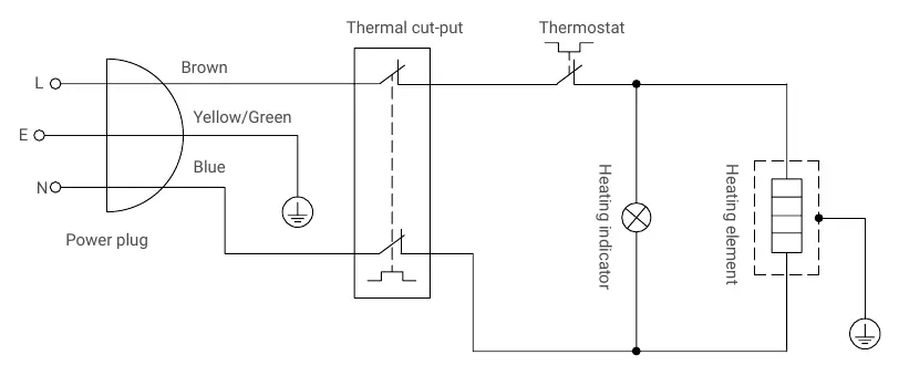
- Wiring diagram illustrates the thermal cut-out, thermostat, heating element, and indicator light connections.
Model compatibility
- Inlet/outlet interface specification is G1/2.
- If water inlet pressure is > 0.55 MPa, an additional pressure limiting valve must be added.

Manual page author
David Miller
Documentation analyst
Organizes user manual content into clear summaries, with attention to model details, product context, and everyday usability.