HVAC / Water Heaters
User Manual for RUUD Tankless Water Heater
Quick guide for the RUUD tankless water heater. Includes installation, venting, gas and water supply connections, operation, maintenance, and troubleshooting.
Table of contents
Manual images
Click an image to enlargeImportant Information
This manual provides essential instructions for the installation, operation, and maintenance of RUUD non-condensing tankless water heaters. Always read and obey all safety messages. Installation and service must be performed by a qualified installer or service agency.
Safety Precautions
- Gas Leaks: If you smell gas, do not light any appliance, do not touch electrical switches, and do not use phones in the building. Call your gas supplier immediately from a neighbor's phone.
- Flammable Materials: Do not store gasoline or other flammable vapors/liquids near the water heater.
- Scalding: Water temperatures above 125°F (52°C) can cause severe burns. Use caution when setting temperatures.
Installation
Choosing a Location
The water heater must be installed in an area where it will not sustain damage from moving vehicles or flooding. Ensure proper clearances from combustible materials. Do not install in areas with corrosive air (e.g., beauty shops, photo labs).
Venting
Direct-vent models must be vented to the outdoors using 3-in./5-in. diameter UL-approved Category III Stainless Steel vent pipe. Do not use other materials. Ensure proper support for vent runs and maintain required clearances.
Gas Supply
Gas piping must conform to local codes and the National Fuel Gas Code. Ensure the gas meter and piping are sized correctly for the total BTU load of all appliances. Perform leak testing using a soapy water solution; never use an open flame.
Water Supply
Use clean, potable water. Inlet water temperatures must be between 32°F (0°C) and 120°F (49°C). Install a pressure-relief valve at the hot water outlet. Insulate both hot and cold water supply lines to prevent freezing.
Electrical Wiring
The unit requires a 120 VAC/60 Hz, 2 Amp power supply. A dedicated circuit is recommended. Do not use 3-prong to 2-prong adapters.
Operation
The water heater is activated by water flow. Use the remote control to set the desired water temperature. The temperature range is 100°F to 120°F (38°C to 49°C), with adjustments up to 140°F (60°C) possible for residential applications by a qualified technician.
Maintenance
- Annual Inspection: Have a qualified technician inspect the venting system, burner, and condensate trap annually.
- Water Filter: Clean the water filter monthly.
- Draining: If the unit will be idle in freezing conditions, drain the water heater completely to prevent damage.
Troubleshooting
If the unit fails to operate, check the troubleshooting chart for common issues like frozen pipes, closed valves, or clogged filters. Error codes displayed on the remote control indicate specific problems; refer to the Service Error Code Chart for solutions.
Practical help
Common problems
Not enough or no hot water
Check if the unit is ON, the water shut-off valve is fully open, the hot water faucet is fully open, or if water piping is frozen.
Water too hot
Decrease the temperature setting at the remote control.
Error code displayed
Refer to the Service Error Code Chart on page 77 for specific error code meanings and solutions.
Fan continues to rotate after faucet is closed
This is normal operation; the post-purge cycle clears flue gases.
Before use
- Is the main gas valve turned on?
- Is the fuse in place or the breaker turned on?
- Does the electronic ignition light?
- Is the water temperature set to a safe level?
- Is the water heater connected to a floor drain?
- Is the water heater properly vented to the outside?
Specs in practice
- Inlet Gas Pressure (Natural Gas)
- 4.0” w.c. – 10.5” w.c.
- Inlet Gas Pressure (LP)
- 8.0” w.c. – 13.0” w.c.
- Electrical Requirement
- 120 VAC/60 Hz, 2 Amps
- Max Temperature Setting
- 120°F (49°C) standard; up to 140°F (60°C) with professional adjustment.
Images and diagrams
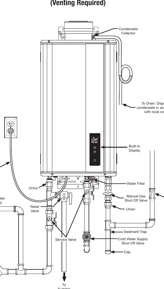
- Typical Direct-Vent installation showing gas, water, and venting connections.
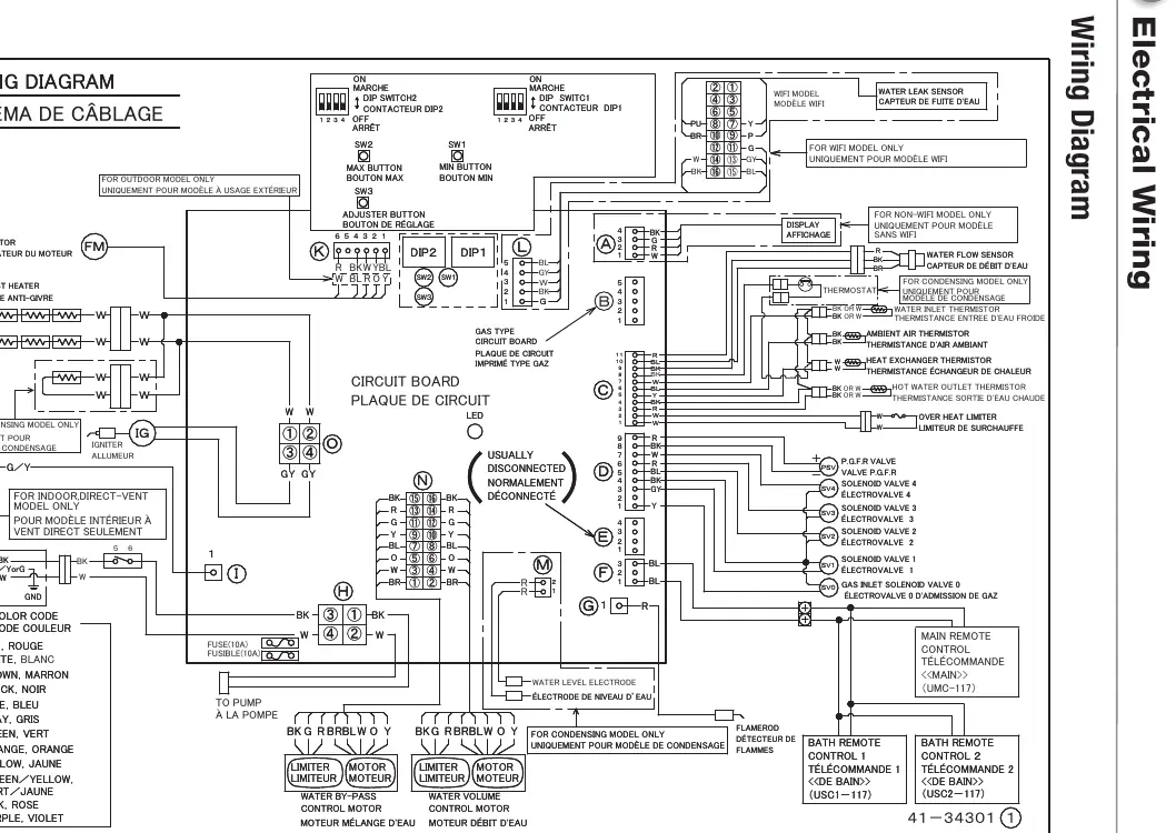
- Wiring diagram for electrical connections.
- Remote control installation steps.
Model compatibility
- For indoor use, use only Category III Stainless Steel vent material.
- Do not use with air handlers or multiple water heater installations for recirculation control.
- Requires 120V power supply.

Manual page author
Emily Carter
User documentation editor
Prepares concise manual descriptions and highlights the most useful setup, operation, and maintenance information for readers.