Industrial / Testing Equipment
User Manual for Huazheng HZ-109S3 Primary Current Injection Test Set
Quick guide for the Huazheng HZ-109S3 Primary Current Injection Test Set. Includes safety precautions, operating instructions, wiring diagrams, and technical specifications.
Table of contents
Manual images
Click an image to enlargeQuick Guide from the Manual
The HZ-109S3 is a high-current generator designed for power system testing, such as CT transformation ratio and contact resistance testing. Before operating, ensure the device is reliably grounded. The power supply must be 380V ±10%. Always set the voltage regulator to zero before connecting the power supply. Do not connect or disconnect test wires while the test is in progress.
Overview
The HZ-109S3 employs ARM chip-controlled output technology and a high-capacity toroidal transformer. It features an LCD ammeter that displays primary and secondary currents as well as the transformation ratio. The unit is housed in an aluminum alloy case with a PC panel.
Main Performance Specifications
- Input Power: AC two-phase 380V, 50A, 50Hz.
- Output Current (Parallel): 3000A at 5V.
- Output Current (Series): 1500A at 10V.
- Primary Current Range: 0-3500A (Resolution: 0.1A).
- Secondary Current Range: 0-6A (Resolution: 0.001A).
- Accuracy: True RMS (0.3% of reading + 0.2% of full scale).
- Operating Environment: -10°C to 40°C, Relative Humidity <80%.
Panel and Function Description
The system consists of a Host Panel and a Voltage Regulator Panel.
Host Panel
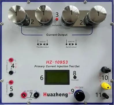
The host panel includes high-current output terminals, a series/parallel connection plate, a secondary current measurement input, a stopwatch input terminal, an LCD screen, and an optical rotary mouse for menu navigation and output control. The grounding terminal must be connected for safety.
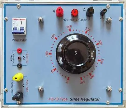
Voltage Regulator Panel
This panel features a power switch for overload protection, working power output terminals, voltage regulator output terminals, and a high-current output adjustment knob. The power input indicator light confirms power supply status.
Usage Instructions
1. Connect the device using the dedicated power input cable, high-current output cable, secondary circuit cable, and grounding cable. If using a power distribution board, ensure the wire cross-section is at least 12.0mm2.
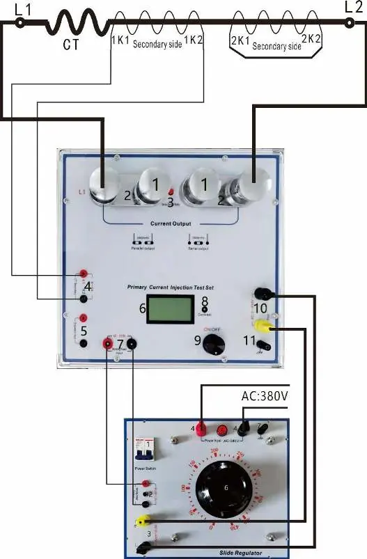
2. Set the voltage regulator to zero and plug in the 380V power supply.
3. Turn on the main switch. The screen will display a welcome message.
4. Use the rotary mouse to change the status from "Start" to "Stop".
5. Adjust the voltage regulator knob to output current. The primary ammeter will display the current value.
6. If the secondary current input cable is connected, the meter will display the secondary current and transformation ratio.
7. For stopwatch operation, connect the stopwatch input cable to the circuit breaker contacts. The instrument defaults to dual-channel mode (internal start, external stop). Press the rotary mouse to toggle between Start/Stop and to reset the stopwatch.
Packing List
- HZ-109S3 High-Current Generator Main Unit
- HZ-10 Contact Voltage Regulator
- High-Current Test Cables
- Dedicated Power Input Cables
- Dedicated Connection Cables
- Grounding Cable
- Connecting Tabs and Clips
- User Manual and Warranty Card
Manufacturer information
Huazheng Electric Manufacturing (Baoding) Co., Ltd.
Practical help
Common problems
Indicator light on the voltage regulator does not turn on
Check the power inlet line; there is no power input to the device.
Output power is insufficient
Ensure the power distribution board wire cross-section is at least 12.0mm2.
Test wires disconnect during operation
It is strictly prohibited to connect or disconnect test wires while the test is in progress.
Before use
- Ensure the device is reliably grounded.
- Verify the power supply is 380V ±10%.
- Use an input power cable with a cross-sectional area greater than 8mm2.
- Use a high-current output cable with a cross-sectional area greater than 250mm2.
- Set the voltage regulator to zero before plugging in the power supply.
Specs in practice
- Parallel Output
- Delivers 3000A at 5V.
- Series Output
- Delivers 1500A at 10V.
Images and diagrams
- Host Panel: Shows terminals for current output, secondary measurement, and rotary mouse control.
- Voltage Regulator Panel: Shows power switch, output terminals, and adjustment knob.
- Wiring Diagram: Illustrates connection between regulator, main unit, and test object.
- Stopwatch Wiring: Shows how to connect the stopwatch to the circuit breaker contacts.
Model compatibility
- Requires 380V power supply.
- Suitable for CT transformation ratio testing and contact resistance testing.

Manual page author
Michael Turner
Technical manual editor
Reviews PDF manuals for structure, safety notes, and practical product details so readers can find the right information quickly.