Power / Solar Inverters
User Manual for Sol-Ark 15K-2P-LV Hybrid Inverter
Comprehensive installation and operation guide for the Sol-Ark 15K-2P-LV hybrid inverter. Includes wiring diagrams, battery setup, parallel system configuration, and troubleshooting.
Table of contents
Manual images
Click an image to enlargeImportant Information
This manual provides crucial information for installing and operating the Sol-Ark 15K-2P-LV Hybrid Inverter System. Qualified and authorized personnel are required to perform installation and maintenance. Before operating, verify the utility voltage and ensure the inverter's programmed grid type matches your utility. The unit is programmed in 120/240V Split-Phase at 60Hz by default.
Installation
The inverter is rated for outdoor (NEMA 3R/IP65) and indoor installation. Ensure at least 6 inches of vertical clearance and 2 inches of side clearance for heat dissipation. Protect the LCD screen from direct UV exposure.
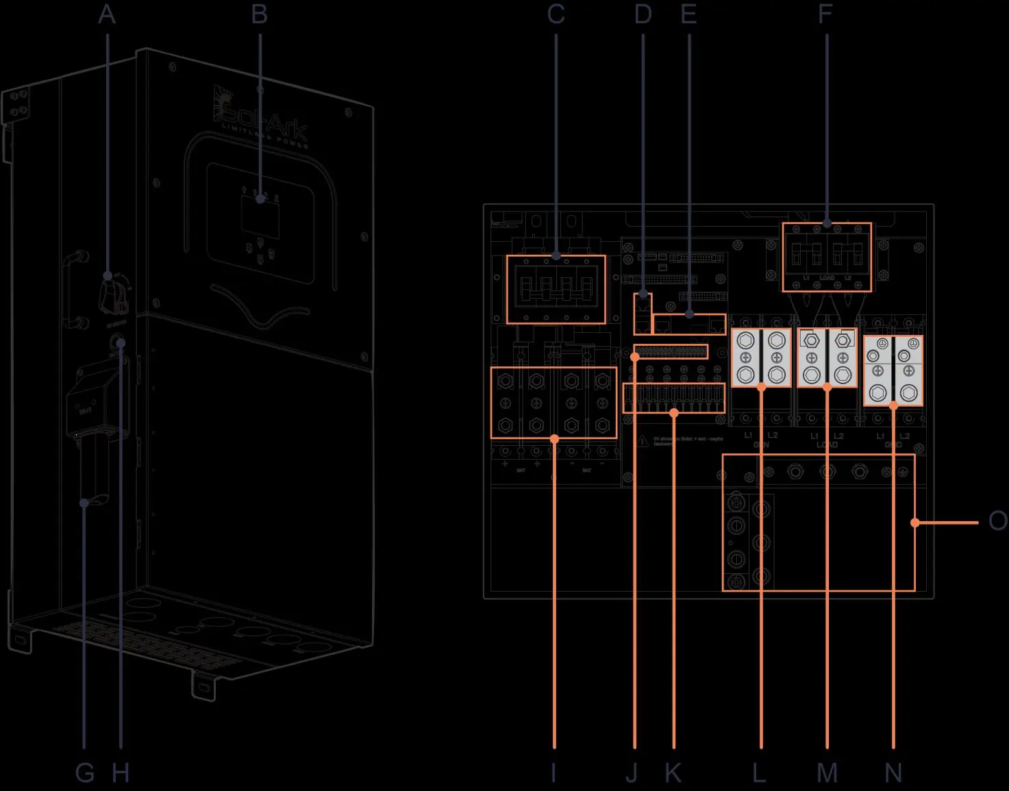
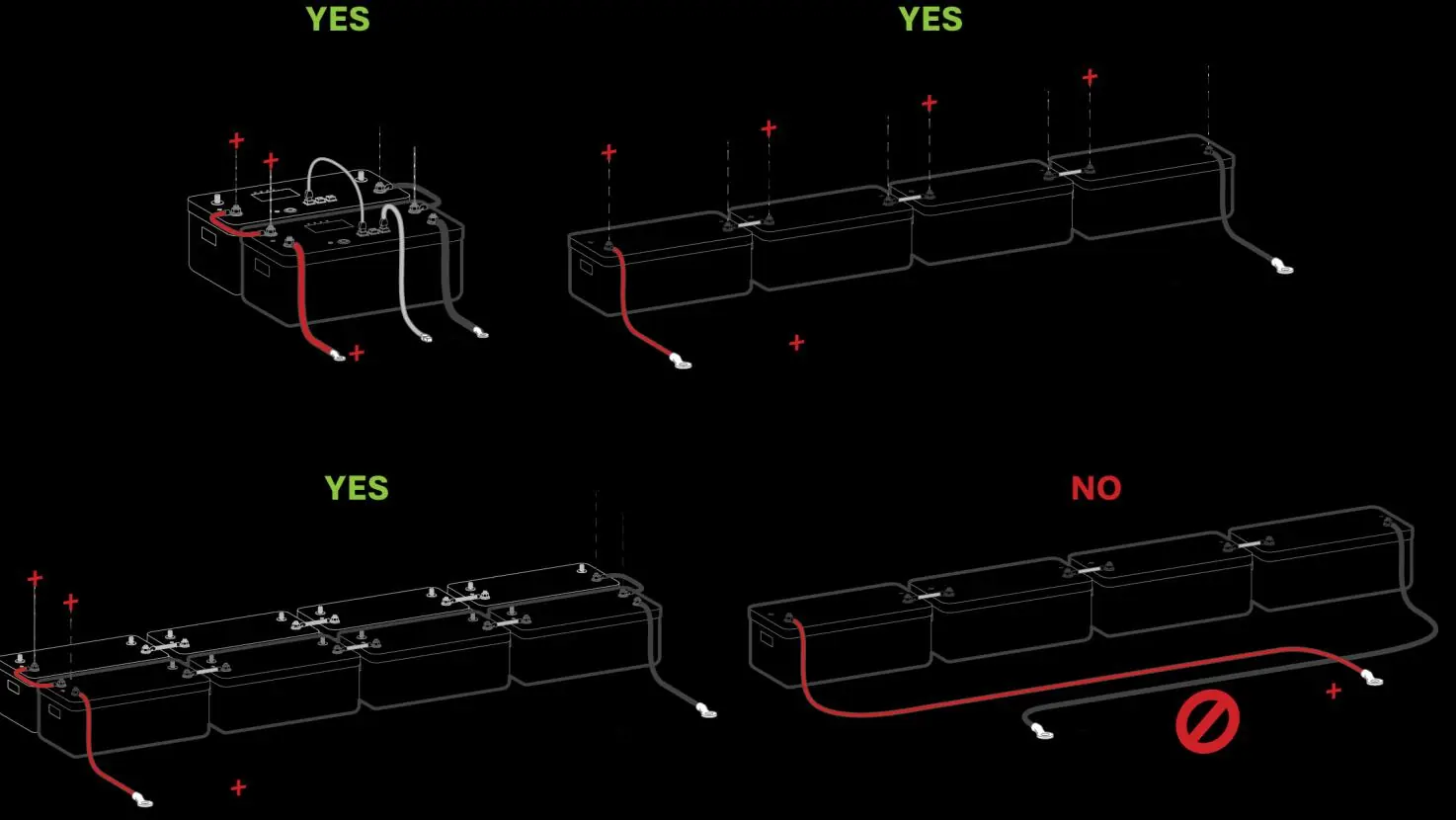
Battery Integration
The system is a 48VDC nominal system. Do not mix battery banks of different make, model, age, or chemistry. Ensure the inverter is OFF while connecting batteries. Use both positive and negative terminals for maximum charge/discharge rates.
PV Connection
The inverter has 3 independent MPPTs supporting up to 2 PV strings each. Max input voltage is 500VDC. Ensure correct polarity; backward polarity will measure 0VDC and cause long-term damage.
Generator Integration
Generators smaller than 19.2kW should connect to the GEN terminal. Generators larger than 19.2kW must connect to the GRID terminal. Ensure the generator has a compatible 2-wire start feature if automatic start is required.
CT Sensors
CT sensors are required for "Limited Power to Home" and "Grid Peak-Shaving" modes. Install sensors on incoming electrical service wires with arrows pointing toward the grid.
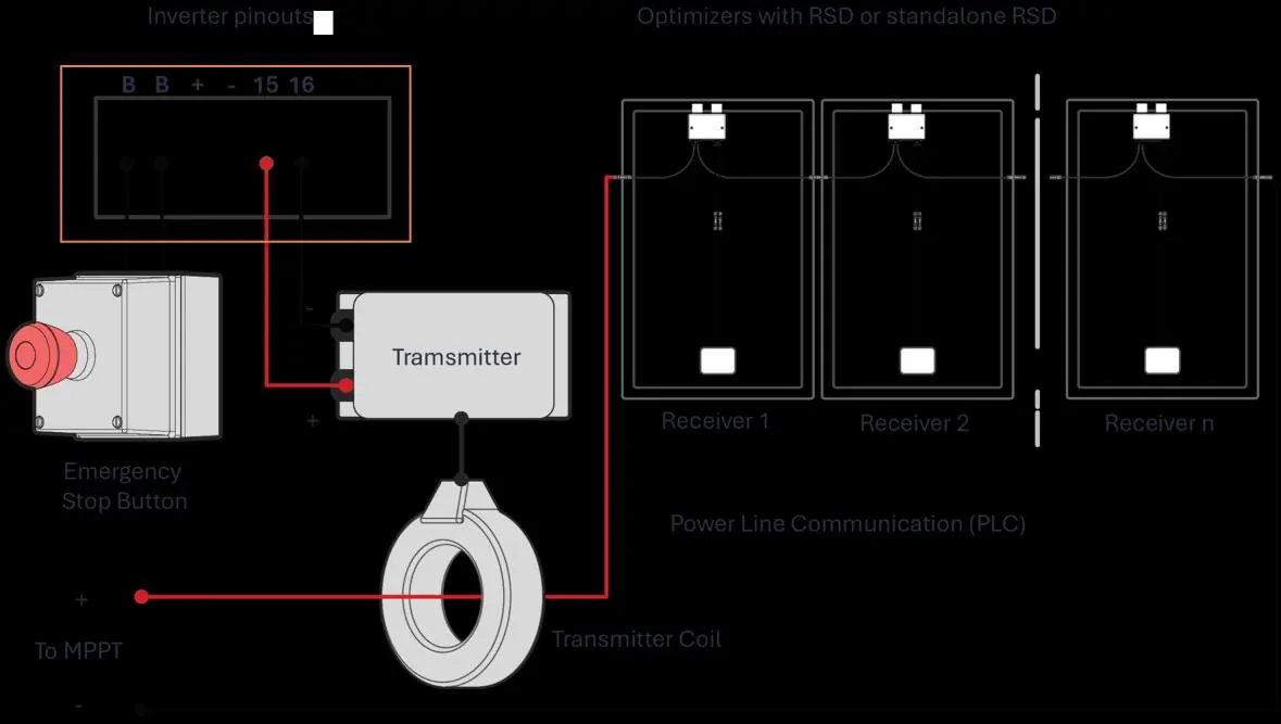
Rapid Shutdown
The inverter supports rapid shutdown via the Emergency Stop pins (B, B). Ensure the transmitter is compatible with the 12VDC power supply (100mA max).
User Interface
The LCD touch screen provides access to system status, alarms, and configuration menus. LED indicators show the status of DC, AC, Normal operation, and Alarm states.
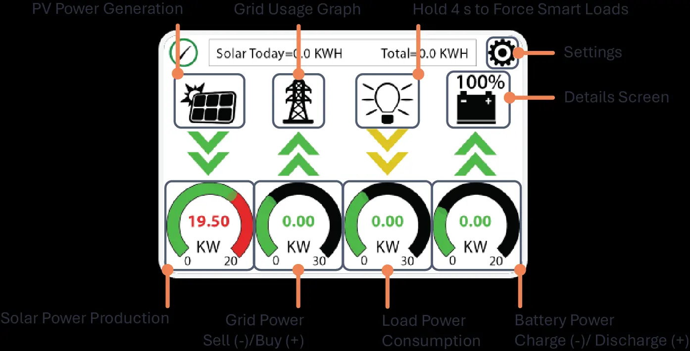
Setup Menus
- Basic Setup: Configure brightness, time sync, and parallel settings.
- Battery Setup: Define battery capacity, charge/discharge limits, and communication protocols.
- Grid Setup: Select grid mode (General Standard, UL1741, etc.) and adjust frequency/voltage ranges.
- Limiter: Configure work modes like Grid Sell, Limited Power to Home, and Time of Use.
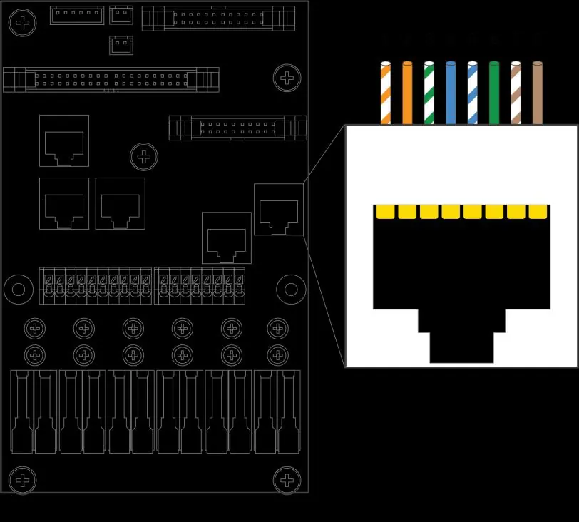
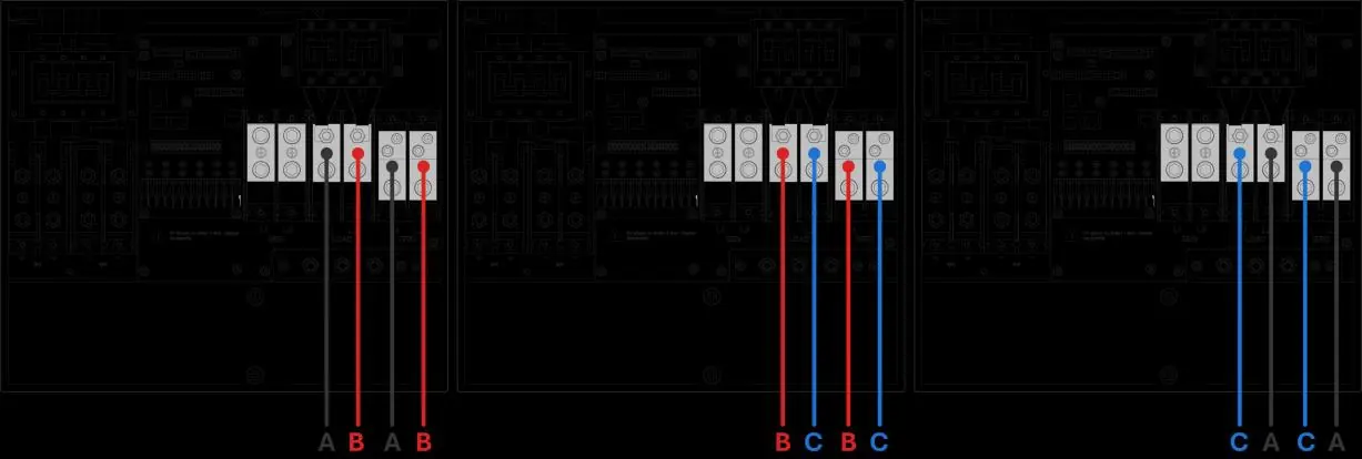
Parallel Systems
Parallel systems require a joint battery bank. All units must have the same software version. Program one unit as "Master" and others as "Slave" using the Modbus SN settings. Connect communication cables in a daisy-chain configuration.
Remote Monitoring
MySolArk allows for remote system monitoring and configuration. Connect the Wi-Fi/Ethernet dongle to the inverter and follow the setup steps in the app or via IP address (10.10.10.1) to connect to a local network.
Troubleshooting
If the system encounters an error, check the Alarms menu. Common issues include:
- LCD not powering on: Check connections (PV/Grid/Battery).
- DC LED not on: Check PV voltage (min 125V) and polarity.
- Grid Phase Wrong: Check phase sequence (AB-BC-CA).
- System beeping: Check the System Alarms menu.
Practical help
Common problems
LCD not powering on
Check all connections; at least one power source (PV, Grid, or Battery) is required.
DC LED indicator is not on
Verify PV input voltage is above 125V and below 500V. Check string polarity on MPPT.
Grid Phase Wrong error
Ensure phase sequence follows AB-BC-CA convention. Check AC connections.
System is beeping
Check the System Alarms menu to identify the triggered alarm.
Before use
- Verify utility voltage before turning ON.
- Check battery voltage (43V-63V).
- Ensure PV input voltage < 500V.
- Confirm CT sensors are installed correctly (arrows toward grid).
- Ensure all wiring is secure and correct.
Specs in practice
- Max Usable PV Power
- 19,500W
- Max Battery Charge/Discharge
- 275A
- Nominal AC Voltage
- 120/240V
- Max Grid Passthrough
- 200A
Images and diagrams
- Standard Wiring Diagram: Shows connections for PV, Battery, Grid, Load, and Generator.
- Parallel Wiring: Shows daisy-chain communication and shared inputs/outputs.
- CT Sensor Installation: Shows correct orientation for grid/generator monitoring.
Model compatibility
- Requires 48V battery system.
- Supports 120/240V split-phase generators.
- Not compatible with 120V single-phase generators.

Manual page author
David Miller
Documentation analyst
Organizes user manual content into clear summaries, with attention to model details, product context, and everyday usability.