Power / Solar Inverters
Quick Start Guide for Sol-Ark 15K-2P-LV Hybrid Inverter
Get started with your Sol-Ark 15K-2P-LV Hybrid Inverter. This quick start guide covers installation, wiring, battery integration, WiFi setup, and system configuration.
Table of contents
Manual images
Click an image to enlargeQuick guide from the manual
This guide provides the essential steps for installing and commissioning the Sol-Ark 15K-2P-LV Hybrid Inverter. It covers site preparation, mounting, wiring, battery integration, and system setup. For advanced configurations and full technical specifications, please refer to the full 15K-2P-LV Installation Manual.
Overview
The Sol-Ark 15K-2P-LV is a hybrid inverter designed for 120/240V split-phase systems. It supports grid-tied, off-grid, and battery backup applications with features like peak shaving, time-of-use, and smart load management.
Installation
Site Preparation
- Ensure 6" of vertical clearance and 2" of side clearance.
- Maintain 6" of side clearance from other systems.
- Protect the LCD screen from direct UV light.
- Operating temperature range: -40 °F to 140 °F.
Mounting
The inverter weighs 135 lbs. Use appropriate hardware for the mounting surface:
- Concrete/Masonry: Minimum (4) M12x60mm expanding anchors.
- Wood Frame: Minimum (5) 1/2" lag screws into at least 2 framing members.
- Metal Frame: Minimum (5) 1/4" self-tapping screws.
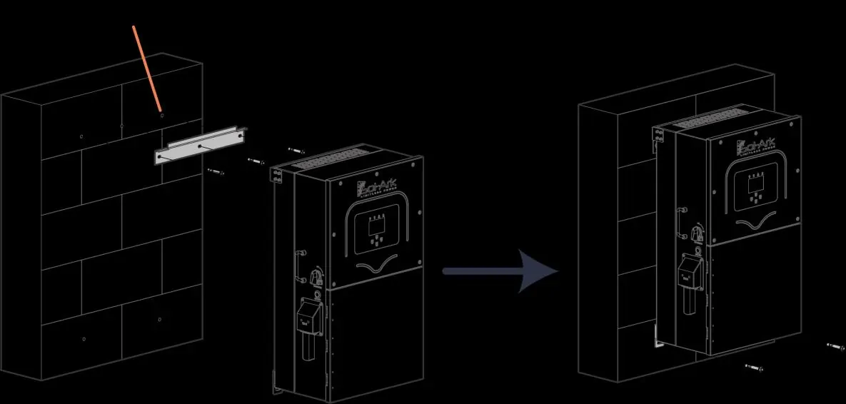
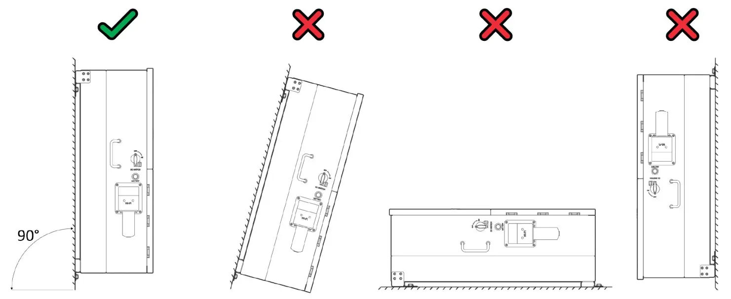
Secure the inverter to the French Cleat using the provided M4x12mm socket head screws. Ensure the unit is in an upright position.
Inverter Wiring
Locate the user wiring area to connect inputs and outputs. Ensure all connections have the correct torque. Do not use impact drivers.
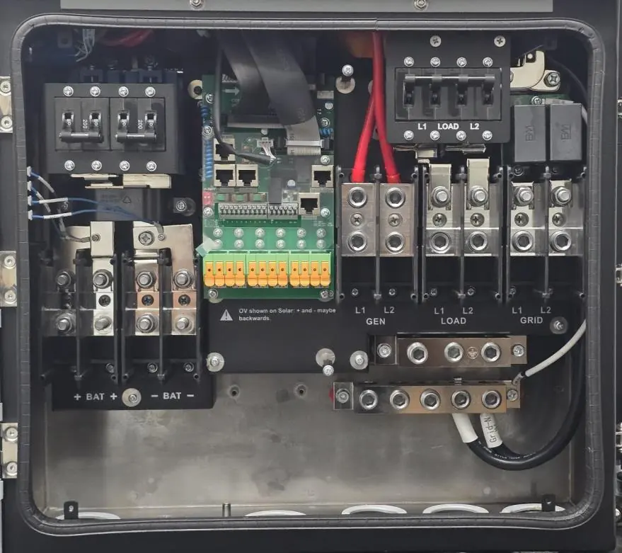
- Battery Input: Connect battery cables to the battery terminals.
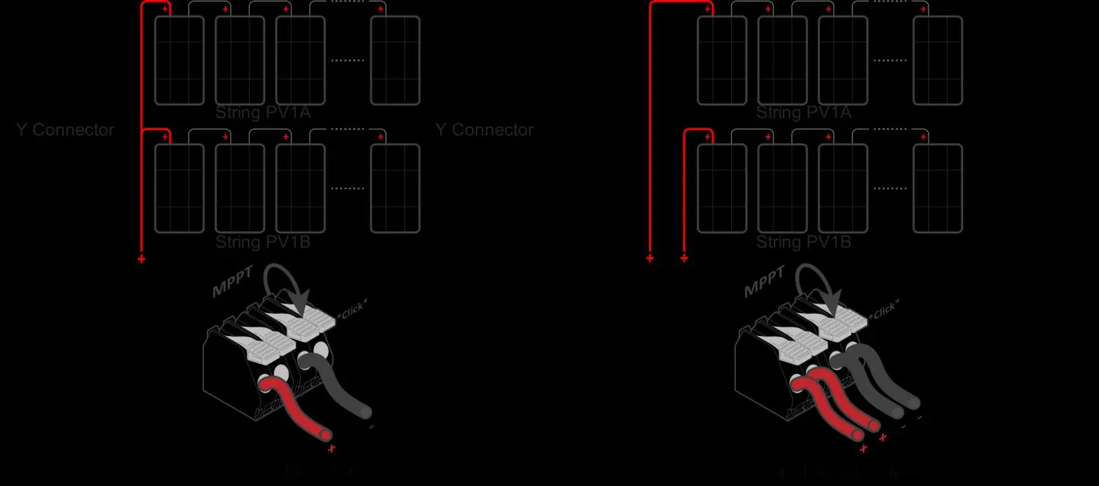
- PV Input: Connect PV strings to the MPPT inputs.
- Grid/Load/Gen: Connect AC lines to the respective terminals.
Battery Integration
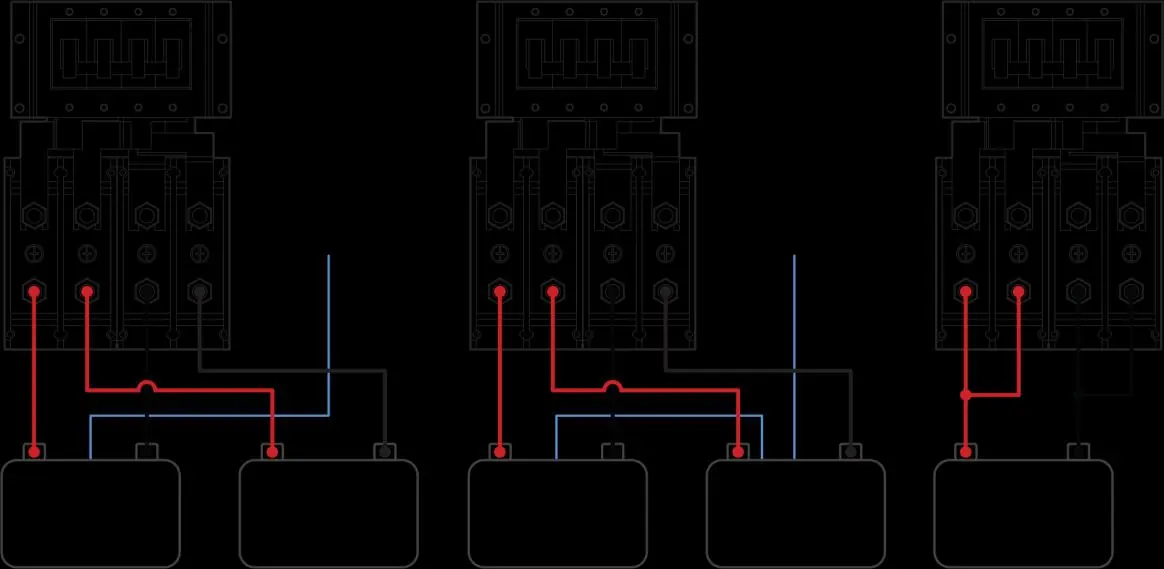
Confirm battery wiring methodology to ensure full 15kW output. Check polarity for each battery connected to the busbar. For closed-loop communication, connect the cable to the BMS port.
System Setup
Battery Communications
Navigate to Settings > Battery Setup on the inverter screen. Configure BMS Lithium Batt settings, activate the battery, and select the appropriate charging method (Use Batt % or Use Batt V Charged).
Grid Parameters
Go to Settings > Grid Param to enable appropriate parameters based on local requirements. Ensure the correct Grid Mode (e.g., General Standard, UL1741 & IEEE1547) is selected.
WiFi Setup
Connect the WiFi dongle to the DP-9 port. Use the MySolArk app or the IP address 10.10.10.1 to configure the network. A solid red LED on the dongle indicates power; a green LED indicates network connection.
Software Updates
Check the current software version by clicking the gear icon on the main screen. Compare this with the latest version on the Sol-Ark website or MySolArk app. If an update is needed, submit an Update Request Form.
Parallel Systems
When using multiple inverters:
- All AC inputs/outputs (Grid, Load, Gen) and batteries must be paralleled.
- PV strings must NOT be paralleled across inverters.
- Configure parallel settings in the Basic Setup screen, designating one unit as Master and others as Slave.
Practical help
Common problems
Inverter not turning on
Check battery voltage on terminals to ensure it is within operating voltage. If waiting more than 3 minutes, verify battery connection.
WiFi connection issues
Ensure the dongle is connected to the DP-9 port. If the app setup fails, use the IP address 10.10.10.1 in a browser to scan for networks.
Battery communication loss
Check BMS settings in the Battery Setup menu and ensure the correct battery protocol is selected.
Before use
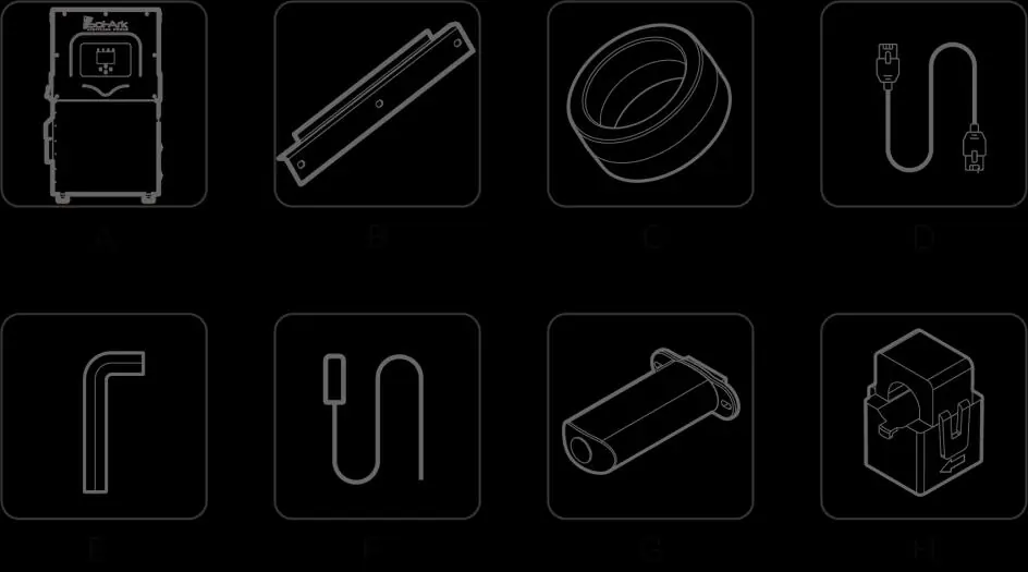
- Confirm all items are in the box (inverter, mounting cleat, toroids, cables, sensors, dongle).
- Create a MySolArk account.
- Prepare the site with required clearances (6" vertical, 2" side).
- Ensure proper mounting hardware for the surface type (concrete, wood, or metal).
- Verify battery wiring polarity and voltage.
- Ensure all AC/DC disconnects are open before checking wires.
Specs in practice
- Max Usable PV Power
- 19.5 kW (± 5%)
- Max Input Current per MPPT
- 26A (self-limiting)
- Max Heat Dissipation
- 2,100W or 7,165BTU/hour
- Continuous GEN input/output
- 80A
Images and diagrams
- Wiring area: Shows battery inputs, MPPT inputs, and terminals for Generator, Load, and Grid.
- Mounting: Illustrates the French Cleat mounting method.
- Battery Integration: Shows wiring for multiple batteries using a busbar.
Model compatibility
- Supports 120/240V Split-Phase generators (smaller than 19.2kW).
- Not compatible with 120V Single Phase or 120/208V 3-Phase generators on GEN port.
- Requires 2.4 GHz WiFi for the dongle.

Manual page author
Michael Turner
Technical manual editor
Reviews PDF manuals for structure, safety notes, and practical product details so readers can find the right information quickly.