Power / Solar Inverters
Installation and User Manual for Sol-Ark 15K Outdoor Inverter
Comprehensive installation and operation guide for the Sol-Ark 15K Outdoor inverter. Includes wiring diagrams, programming instructions, battery setup, and troubleshooting steps.
Table of contents
Manual images
Click an image to enlargeQuick Guide from the Manual
The Sol-Ark 15K Outdoor is a high-capacity solar inverter. Before installation, ensure the unit is mounted in a location protected from direct sunlight with at least 2 inches of clearance on the sides for cooling. Qualified persons only should perform the installation due to high-voltage risks. Always verify that the system is properly grounded and that the neutral is bonded to the ground only once in the circuit.
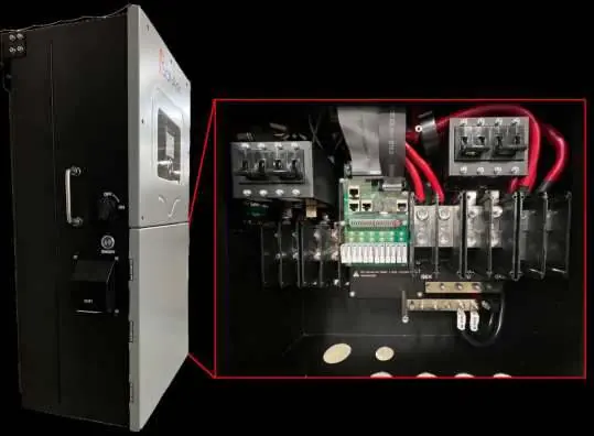
Inverter Components
The unit features an LCD touch screen for programming, a PV disconnect switch, and an ON/OFF button. Key connection areas include the 250A battery breaker, communication ports, MPPT inputs, and terminal blocks for Grid, Load, and Generator connections.
Physical Installation
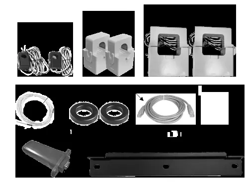
Mount the inverter using the provided French Cleat. Ensure the unit is level. When connecting batteries, use the included toroids on battery input cables. The system is a 48V nominal system; do not exceed 4 batteries in series for 12V units. Always use strain reliefs on all wires entering or exiting the user area.

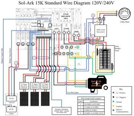
Wiring Diagrams
The manual provides specific wiring diagrams for various configurations, including standard 120V/240V systems, off-grid setups, and AC-coupled systems. Ensure all AC wires use conduit or double-insulated wire. CT sensors must be installed on L1 and L2 upstream of the main service panel for features like Peak Shaving and Limited to Home mode.
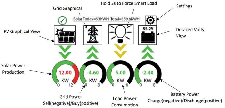
Programming and GUI
The LCD touch screen allows for comprehensive system configuration. Key menus include:
- Basic Setup: Adjust brightness, time, load limit power, and parallel system settings.
- Battery Setup: Configure battery capacity, charge/discharge rates, and charging voltages (Bulk, Absorption, Float).
- Grid Setup: Configure grid frequency, grid type, and power modes (Limited Load, Limited to Home, Grid Sell, Time of Use).
Generator Integration
The Sol-Ark 15K supports generator integration via the GEN terminal block. For generators <10kW, use the GEN breaker. For standby generators >10kW, use the GRID breaker. Ensure the generator has two-wire start compatibility for automatic generator start (AGS) functionality.
Troubleshooting
If the system displays an error, consult the error code table. Common issues include:
- LCD not powering on: Check all power source connections (PV/Grid/Battery).
- Grid Phase Wrong: Indicates a wiring issue; verify L1/L2 connections between Grid and Load breakers.
- System beeping: Check the alarms menu; if no battery is connected, ensure 'No Battery' is selected in settings.
- Panels not producing: Check PV disconnect switch and ensure PV voltage is within 150V-425V.
Maintenance and Warranty
Regularly check the system using the Install Verification Checklist. The unit comes with a 10-year limited warranty. Returns require a Return Material Authorization (RMA) number. Contact Sol-Ark support at 1-972-575-8875 or [email protected] for assistance.
Practical help
Common problems
LCD not powering on
Check all connections (PV/Grid/Battery) and press the power button.
Grid Phase Wrong error
Wiring issue; measure L1/L2 between Grid and Load breakers to ensure 0V AC.
System beeping
Check alarms menu; if no battery is connected, ensure 'No Battery' is selected in settings.
Panels not producing
Check PV disconnect switch, wiring, and ensure PV voltage is within 150V-425V.
Before use
- Ensure LCD is protected from direct sunlight.
- Verify 2-inch clearance on left and right for cooling.
- Tighten all battery lugs.
- Ensure Ground and Neutral are bonded only once.
- Check PV voltage is below 500Voc.
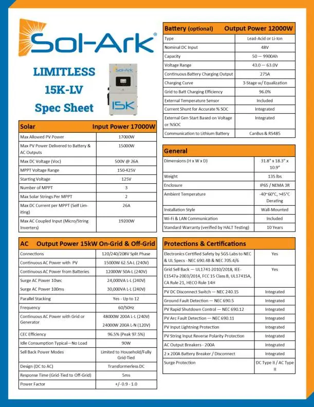
Specs in practice
- Max PV Input
- 17,000W total, 5.67kW per MPPT.
- Max AC Output
- 15kW continuous.
- Battery Voltage
- 48V nominal (43V-63V range).
- Enclosure Rating
- IP65 / NEMA 3R (Outdoor rated).
Images and diagrams
- Wiring Diagrams: Examples for standard, off-grid, and AC-coupled systems are provided on pages 8-16.
- CT Sensor Wiring: L1 to pins 3/4, L2 to pins 5/6; ensure correct direction (arrow points to grid).
Model compatibility
- Batteries: 48V system; do not exceed 4 batteries in series for 12V units.
- Generators: Supports 240V/208V generators; requires two-wire start for auto-start functionality.

Manual page author
Michael Turner
Technical manual editor
Reviews PDF manuals for structure, safety notes, and practical product details so readers can find the right information quickly.