HVAC / Heat Pumps
Installation Guide for Ideal Push-In Wire Connectors (Models 32-90)
A comprehensive installation guide for Ideal Push-In Wire Connectors (Models 32, 33, 34, 87, 88, 90). Includes step-by-step wiring instructions, safety warnings, wire stripping requirements, and technical specifications.
Quick answers from the manual
Quick answer
- To install, strip 13mm of insulation from the copper wire and push it firmly into an open port. Ensure power is off before starting. p. 1
Key actions
- Strip wire insulation p. 1
- Remove wire p. 1
Problems and fixes
Removing a wire
Pull and twist the wire back and forth to release it from the port.
p. 1Maintenance and reset
- Reusing connectors p. 1
Technical specifications
| Parameter | Value | Meaning | Pages |
|---|---|---|---|
| Models 32, 33, 34 Rating | 32 Amp / 450V / 105°C | Maximum electrical ratings | p. 1 |
| Models 87, 88, 90 Rating | 24 Amp / 450V / 105°C | Maximum electrical ratings | p. 1 |
Where to find it in the PDF
- Installation Instructions p. 1
Table of contents
Manual images
Click an image to enlargeQuick guide from the manual
These connectors are designed for copper-to-copper connections only. Before starting, ensure the power is turned off. Strip the wire insulation to exactly 13mm. Insert the wire firmly into an open port. Use only one conductor per port. These connectors are suitable for solid and semi-rigid conductors (less than 7 strands) but are not rated for flexible cables with more than 7 strands.
Installation instructions
- Turn off power: Always disconnect power before installing or removing connectors.
- Strip wire: Remove 13mm of insulation from the wire.
- Insert: Grip the wire firmly and push the conductor into an open port.
- Check: Ensure only one conductor is used per port.
Removal instructions
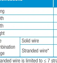
To remove a wire from the connector, pull and twist the wire back and forth while pulling it out. If using pliers for assistance, ensure you do not damage the connector. Note that connectors are reusable on solid wires of the same gauge or larger, but you must cut and re-strip the wire before reuse. Do not reuse connectors on stranded wire.
Technical specifications
The connectors are divided into two rating groups:
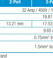
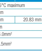
- Models 32, 33, 34: 32 Amp / 450V / 105°C maximum.
- Models 87, 88, 90: 24 Amp / 450V / 105°C maximum.
- Wire range (Solid): 0.75mm² to 4.0mm².
- Wire range (Stranded): 1.5mm² to 2.5mm² (limited to ≤ 7 strands).
Safety warnings
- Copper only: Do not use on aluminum wire.
- Strand limit: Not suitable for flexible cable with >7 strands.
- Fire hazard: Incorrect use can cause electrical fires, personal injury, or death.
- Reuse policy: Do not reuse connectors on stranded wire.
Practical help
Common problems
Using on aluminum wire
Do not use. These connectors are for copper-to-copper connections only.
Using on flexible cable with >7 strands
These connectors are not rated for flexible cables with more than 7 strands.
Reusing connector on stranded wire
Do not reuse the connector if it was previously used on stranded wire.
Before use
- Turn off the electrical power supply.
- Verify the wire is solid or semi-rigid (<7 strands).
- Strip the wire insulation to 13mm.
- Ensure the wire is copper.
- Check that the connector rating matches your electrical requirements.
Images and diagrams
- The strip length diagram shows a 13mm measurement mark.
- The insertion diagram shows the wire being pushed straight into the port.
- The removal diagram illustrates the pull-and-twist motion required to release the wire.
Model compatibility
- Compatible with solid and semi-rigid conductors (<7 strands).
- Not compatible with aluminum wire.
- Not compatible with flexible cables >7 strands.

Manual page author
David Miller
Documentation analyst
Organizes user manual content into clear summaries, with attention to model details, product context, and everyday usability.