Electronics / Cordless Phones
Anker 2.4G Wireless Mouse Sensor Replacement Guide
A step-by-step repair guide for replacing the sensor in an Anker 2.4G wireless mouse, including required tools, disassembly instructions, and soldering procedures.
Quick answers from the manual
Quick answer
- To replace the sensor, you must disassemble the mouse housing, disconnect the internal wires, remove the motherboard, and desolder the six wires holding the I.C. chip. p. 1, 6
Key actions
- Remove the four screws located under the stickers on the bottom of the mouse. p. 3
- Disconnect the wires from the white crimping headers. p. 4
- Desolder the six wires holding the I.C. chip. p. 6
Problems and fixes
Solder connections bridged
Ensure no solder connections are bridged as this can cause serious damage to your mouse.
p. 6Show 1 more answers Show less
Where to find it in the PDF
- Introduction and Tools p. 2
- Disassembly Steps p. 3, 4, 5
- Sensor Replacement p. 6
Table of contents
Manual images
Click an image to enlargeQuick guide from the manual
This document provides instructions for replacing the sensor on an Anker 2.4G wireless mouse. The process involves disassembling the mouse housing, disconnecting internal components, and desoldering/soldering the sensor chip. Caution: This procedure requires the use of a soldering iron and should be performed with care to avoid damaging the device.
Tools and Parts
Before beginning, ensure you have the following tools and parts:
- Phillips #0 screwdriver
- Soldering workstation
- Desoldering braid
- Small plastic spudger
- Anti-static wrist strap
- Replacement IC chip
Disassembly
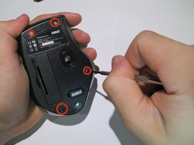
- Remove Screws: Use a spudger to carefully pry off the stickers on the bottom of the mouse to reveal the four screws. Use a Phillips #0 screwdriver to remove them.
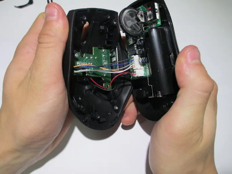
- Open Housing: Use a spudger to gently pry apart the upper and lower housing. Avoid using excessive pressure to prevent warping the plastic.
- Disconnect Wires: Carefully disconnect the wires from the white crimping headers. Pull as far up on the wire as possible to avoid ripping them.
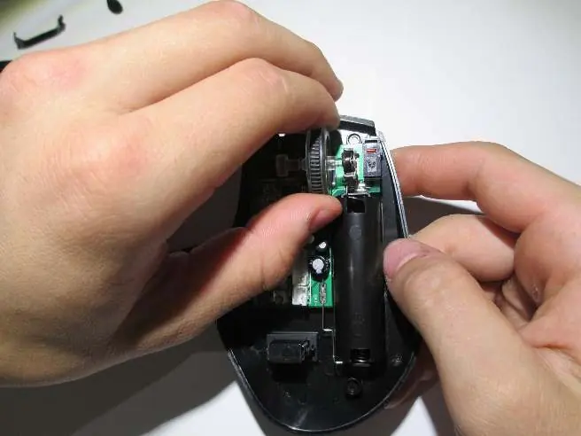
- Remove Scroll Wheel: Pull the scroll wheel to the left to remove it from the motherboard. Pull parallel to the board, not perpendicularly.
- Remove Motherboard: Gently lift the motherboard away from the plastic housing. Use an anti-static wrist strap to prevent electrostatic discharge.
Sensor Replacement
Once the motherboard is removed:
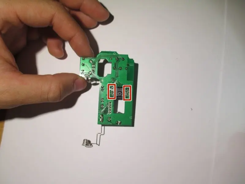
- Desolder: Use your soldering workstation and desoldering braid to desolder the six wires holding the I.C. in place.
- Replace: Remove the broken sensor and install the new sensor.
- Solder: Solder the new sensor back into place. Ensure that none of the solder connections are bridged, as this can cause serious damage to the mouse.
Reassembly
To reassemble your device, follow the disassembly instructions in reverse order.
Manufacturer information
iFixit
Practical help
Common problems
Solder bridging
Ensure no solder connections are touching each other after soldering, as this can cause serious damage.
Warped plastic housing
Do not use excessive pressure when prying apart the housing with the spudger.
Damaged wires
Pull as far up on the wire as possible when disconnecting from headers to avoid ripping.
Before use
- Check the battery casing for any corrosion or visible damage.
- Wear an anti-static wrist strap to prevent electrostatic discharge.
- Ensure you have a soldering workstation and desoldering braid ready.
- Use a Phillips #0 screwdriver for the housing screws.
Show more Show less
Images and diagrams
- The guide includes images showing the exact location of the four screws under the stickers.
- Images illustrate the correct method for prying the housing apart.
- Visuals show the specific white crimping headers for wire disconnection.
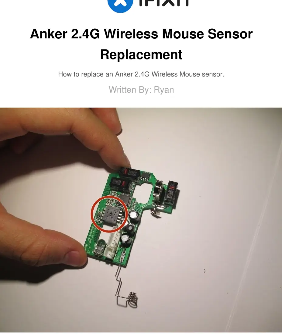
- The final steps show the motherboard and the specific I.C. chip to be desoldered.
Model compatibility
- This guide is specifically for the Anker 2.4G Wireless Mouse.

Manual page author
Emily Carter
User documentation editor