Electronics / Networking
User Manual for Intellinet 10-Port Switch 562218
Quick guide for the Intellinet 10-Port Switch (Model 562218). Learn about LED indicators, port connections, installation requirements, and troubleshooting.
Table of contents
Manual images
Click an image to enlargeQuick guide from the manual
This document provides essential setup and operational information for the Intellinet 10-Port Switch (Model 562218). Before using the device, ensure it is placed on a stable surface with adequate ventilation and away from sources of electrical interference. The switch supports Auto-MDI/MDI-X, allowing for flexible cable connections.
Connections and Indicators
The front panel features LED indicators to help monitor the status of the switch and its connections.

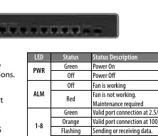
- PWR (Power): Green indicates the device is powered on; Off indicates it is powered off.
- ALM (Alarm): Off indicates the fan is working correctly. Red indicates the fan is not working and maintenance is required.
- Ports 1-8: Green indicates a valid connection at 2.5/5/10G. Orange indicates a valid connection at 100/1000M. Flashing indicates data transmission. Off indicates no link.
- Ports 9-10S: Green indicates a valid connection at 1/10G. Flashing indicates data transmission. Off indicates no link.
Installation
To ensure optimal performance and longevity of the switch, follow these installation guidelines:
- Place the switch on a level surface capable of supporting its weight.
- Maintain at least 25 mm (approx. 1 inch) of clearance around the device for proper ventilation.
- Keep the switch away from sources of electrical noise, such as radios, transmitters, and broadband amplifiers.
- Ensure the switch is within 100 meters (approx. 328 feet) of the network devices to be connected.
- Attach the included rubber feet to the bottom corners of the switch to increase stability.
Power and Connectivity
Use the included power cord to connect the switch to an AC outlet. Verify that the PWR LED on the front panel is lit. All RJ45 ports support Auto-MDI/MDI-X functionality, meaning you can use either straight or crossover UTP/STP cables to connect to PCs, routers, hubs, or other switches. Cat5e, Cat6, or Cat6a UTP/STP cables are recommended for optimal performance.
Manufacturer information
Intellinet Network Solutions
Practical help
Common problems
Status LED does not indicate a link or activity
Check the corresponding connected device for proper setup, configuration, and power.
ALM LED is red
The fan is not working; maintenance is required.
No power indication
Confirm the power cord is securely connected to an AC outlet and the PWR LED is lit.
Before use
- Ensure the surface is level and can support the weight of the switch.
- Provide at least 25 mm of clearance for ventilation.
- Keep the device away from electrical noise sources (radios, transmitters).
- Ensure network devices are within 100 m of the switch.
- Attach the provided rubber feet to the bottom corners.
Specs in practice
- Auto-MDI/MDI-X
- Allows the use of both straight and crossover UTP/STP cables.
Images and diagrams
- The front panel contains the RJ45 ports and LED indicators for power, alarm, and port status.
- Rubber feet are attached to the bottom corners to prevent sliding and improve stability.
Model compatibility
- Compatible with Cat5e, Cat6, and Cat6a UTP/STP cables.
- Supports connection to PCs, routers, hubs, and other switches.

Manual page author
David Miller
Documentation analyst
Organizes user manual content into clear summaries, with attention to model details, product context, and everyday usability.