Automotive / Car Audio
JL Audio 12W1v3-2 / 12W1v3-4 Subwoofer Driver Owner's Manual
Quick guide for the JL Audio 12W1v3-2 and 12W1v3-4 subwoofer drivers. Includes physical specifications, enclosure recommendations, power range guidelines, and installation safety tips.
Table of contents
Manual images
Click an image to enlargeQuick Guide from the Manual
The JL Audio 12W1v3 series subwoofers are high-performance drivers designed for automotive use. To ensure optimal performance and longevity, it is critical to match the amplifier power correctly and build an enclosure that meets the specific volume requirements for either sealed or ported designs. Always secure the enclosure firmly to the vehicle frame to prevent it from becoming a projectile in the event of a collision.
Physical Specifications
The 12W1v3 series requires specific mounting dimensions for proper installation:
- Nominal Diameter: 12.0 inches (300 mm)
- Overall Diameter: 12.50 inches (318 mm)
- Mounting Hole Diameter: 11.0625 inches (281 mm)
- Bolt Hole Circle: 11.7 inches (297 mm)
- Magnet Diameter: 5.25 inches (133 mm)
- Mounting Depth: 5.41 inches (137 mm)
- Net Weight: 12.2 lbs (5.5 kg)
Enclosure Recommendations
The manual provides two recommended enclosure types. All volumes listed are net internal volumes; you must account for box, port, and brace displacement when building.
- Sealed Enclosure: Recommended for tight spaces. Provides excellent sound quality. Net internal volume: 1.10 ft³ (31.15 liters).
- Ported Enclosure: Provides 3dB more output at the same power. Net internal volume: 1.6 ft³ (45.3 liters).
Important Construction Notes:
- Use material at least 5/8 inch (16mm) thick. If using 5/8 inch material, subtract 1/4 inch (6.5mm) from each dimension.
- Do not use material thinner than 5/8 inch as it may compromise rigidity.
- When using two subwoofers in a common enclosure, double the required volume and, for ported designs, use two times the recommended port(s).
Power Handling Guidelines
The manual defines a power range for the driver to ensure reliability:
- Minimum (Medium Gray): Comfortable operating range, will not stress the woofer but may not extract full performance.
- Optimum (Light Gray): Best compromise between reliability, high output, and low distortion.
- Maximum (Dark Gray): Slightly more SPL, but operate with caution.
- Warranty Void (Black): Operating in this zone carries a high probability of failure due to heat or mechanical stress.
Installation and Safety
Prolonged exposure to sound pressure levels exceeding 100dB can cause permanent hearing loss. When installing the subwoofer in a vehicle, it is extremely important to secure the enclosure firmly. JL Audio recommends bolting the enclosure through the metal of the floorpan or the vehicle frame using large diameter washers for reinforcement.
Compatibility
This speaker is recommended for use in bi-amplified systems using high-quality satellite speakers and amplifiers. The use of a passive crossover (coil) is not recommended as it will adversely affect performance.
Manufacturer information
JL Audio
Practical help
Common problems
Subwoofer performance is unsatisfactory
Ensure the amplifier power is within the 'Optimum' range. Using less than the minimum power will not damage the woofer but will result in poor performance.
Enclosure rigidity issues
Ensure you are using material at least 5/8 inch (16mm) thick. Thinner material may compromise the enclosure's structural integrity.
Risk of enclosure movement during collision
Secure the enclosure firmly by bolting it through the metal floorpan or vehicle frame using large diameter washers.
Before use
- Verify the amplifier power matches the driver's continuous power rating.
- Calculate system impedance and the total number of subwoofers.
- Choose between a sealed or ported enclosure based on available space.
- Ensure enclosure material is at least 5/8 inch thick.
- Account for box, port, and brace displacement when calculating gross internal volume.
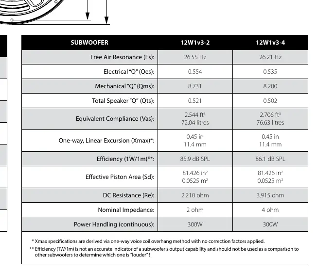
Specs in practice
- Fs (Free Air Resonance)
- The frequency at which the speaker resonates in free air.
- Vas (Equivalent Compliance)
- The volume of air that has the same compliance as the speaker suspension.
- Xmax (Linear Excursion)
- The maximum one-way linear movement of the voice coil.
- Re (DC Resistance)
- The electrical resistance of the voice coil.
Images and diagrams
- Physical Specs Diagram: Illustrates dimensions A (Overall), B (Mounting Hole), C (Bolt Circle), D (Magnet), and E (Mounting Depth).
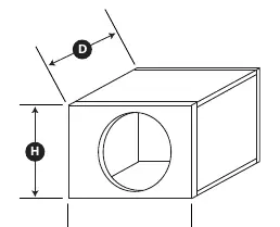
- Sealed Enclosure Diagram: Shows the box dimensions (W, H, D) required for the sealed configuration.
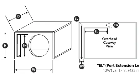
- Ported Enclosure Diagram: Shows the box dimensions (W, H, D) and internal port dimensions (SW, SH, SL) required for the ported configuration.
Model compatibility
- Recommended for bi-amplified systems.
- Not recommended for use with passive crossovers (coils).

Manual page author
David Miller
Documentation analyst
Organizes user manual content into clear summaries, with attention to model details, product context, and everyday usability.