Tools / Electronic Test Equipment
Instruction Manual for Kyoritsu KEW 2009R Digital Clamp Meter
Comprehensive user guide for the Kyoritsu KEW 2009R Digital Clamp Meter. Includes setup, measurement procedures for current, voltage, resistance, and frequency, safety warnings, and maintenance instructions.
Quick answers from the manual
Quick answer
- The Kyoritsu KEW 2009R is a digital clamp meter for measuring AC/DC current and voltage, resistance, continuity, and frequency. It features True-RMS detection, peak/average modes, and a data hold function. p. 1, 7
Key actions
- Measure DC Current p. 15
- Measure AC Current p. 16
- Replace Battery p. 28
First start
- Set function selector to desired range. Check display for 'BATT' warning. If clear, proceed. p. 14
Problems and fixes
Display blank
Check battery or Auto-power-off (turn switch OFF then back on).
p. 14
Inaccurate reading
Ensure jaws are fully closed.
p. 16Maintenance and reset
- Zero Adjust/Reset button is used for zero adjustment on DCA and resistance ranges, and to reset PEAK mode. p. 12
Technical specifications
| Parameter | Value | Meaning | Pages |
|---|---|---|---|
| Max Conductor Size | 55mm | Maximum diameter of conductor that can be clamped. | p. 10 |
| Power Source | Two 1.5VDC R6P batteries | Required batteries for operation. | p. 10 |
| Auto-power-off | 10 minutes | Time until automatic shutdown. | p. 10 |
Where to find it in the PDF
- Instrument Layout p. 11
- DC Current Measurement p. 15
- Battery Replacement p. 28
Table of contents
Manual images
Click an image to enlargeQuick Guide
The Kyoritsu KEW 2009R is a digital clamp meter designed for measuring AC/DC current and voltage, resistance, continuity, and frequency. Before use, ensure the battery is installed and the function selector switch is set to the desired position. Always check for the 'BATT' warning on the display; if present, replace the batteries. Ensure the Data Hold function is disabled before starting measurements.
Instrument Layout
The device features the following key components:
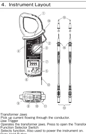
- Transformer Jaws: Used to pick up current flowing through the conductor.
- Jaw Trigger: Opens the transformer jaws.
- Function Selector Switch: Selects the measurement function and powers the instrument.
- Data Hold Button: Freezes the display reading.
- Digital Display: Shows measurement values and status indicators.
- Terminals: V/Ω and COM terminals for test leads.
Preparation for Measurement
Before performing measurements, verify the following:
- Battery Check: Set the switch to any position other than OFF. If the display is clear and no 'BATT' symbol appears, the battery is sufficient.
- Switch Setting: Ensure the function selector switch is set to the correct position and the Data Hold function is disabled.
Measurement Procedures
DC Current Measurement
- Set the function selector switch to the DCA position.
- Press the Zero Adjust/Reset button for about one second to zero the display (400A range only).
- Press the trigger to open the jaws and clamp them onto the conductor.
- Take the reading. Keep the conductor at the center of the jaws for accuracy.
AC Current Measurement
- Set the function selector switch to the ACA position.
- Press the trigger to open the jaws and clamp them onto a single conductor.
- Take the reading.
Voltage Measurement (DC/AC)
- Set the function selector switch to the appropriate DCV or ACV position.
- Slide the terminal cover to disclose the V/Ω and COM terminals.
- Plug the red test lead into the V/Ω terminal and the black test lead into the COM terminal.
- Connect the test leads to the circuit under test and take the reading.
Resistance and Continuity
- Set the function selector switch to the Ω position.
- Connect test leads to the V/Ω and COM terminals.
- Short the test leads and press the Zero Adjust/Reset button to offset lead resistance.
- For continuity, press the mode selector button to enter continuity mode. The buzzer will sound if resistance is 20.0Ω or less.
Other Functions
- Peak Measurement: Captures the peak value of the input signal. Available on DCA, ACA, DCV, and ACV ranges.
- Average Measurement: Displays a running average of six readings over about 2 seconds.
- Data Hold: Freezes the current reading on the display.
- Auto-power-off: Automatically turns off the instrument after about 10 minutes of inactivity.
Battery Replacement
If the battery voltage is too low, the 'BATT' symbol appears. To replace:
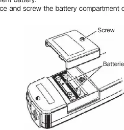
- Set the function selector switch to OFF.
- Remove the test leads.
- Unscrew and remove the battery compartment cover on the bottom.
- Replace with new R6P or equivalent batteries, observing correct polarity.
- Re-place and screw the cover back on.
Practical help
Common problems
Display is blank or 'BATT' is shown
Replace the batteries (R6P or equivalent) as the voltage is too low.
Inaccurate current reading
Ensure the transformer jaws are fully closed and the conductor is positioned in the center of the jaws.
No output from OUTPUT terminal
Ensure the output lead is properly connected and the instrument is set to a current range (ACA/DCA).
Before use
- Check battery voltage (ensure no BATT warning).
- Verify function selector switch is in the correct position.
- Ensure Data Hold function is disabled.
- Inspect test leads for damage.
- Ensure transformer jaws are clean and close properly.
Specs in practice
- CAT IV 600V / CAT III 1000V
- Safety rating indicating the instrument's ability to withstand electrical surges in specific environments.
Images and diagrams
- Instrument Layout: Identifies the jaws, trigger, selector switch, display, and terminals.
- Measurement Diagrams: Illustrates the correct way to clamp the conductor (centered) versus the wrong way.
- Battery Replacement: Shows the location of the battery compartment screw and battery orientation.
Model compatibility
- Maximum conductor size: 55mm diameter.
- Output terminal is for current ranges only.
- Auto-power-off is disabled in PEAK mode.

Manual page author
Michael Turner
Technical manual editor
Reviews PDF manuals for structure, safety notes, and practical product details so readers can find the right information quickly.