Tools / Measuring Tools
User Manual for AEMC Current Probes and Sensors
Comprehensive user guide for AEMC current probes and sensors. Includes installation, operation, safety precautions, maintenance, and technical specifications for models 193-24-BK, E94, MN93-BK, and others.
Quick answers from the manual
Quick answer
- These current probes and sensors are designed for use with AEMC power quality meters and energy loggers. They allow for non-invasive current measurement on conductors. p. 1
Key actions
- Connect the probe to the instrument with arrows pointing toward the load. p. 17
First start
- Connect the probe to the instrument, ensure the jaws are closed, and perform zero adjustment if required by the model. p. 17, 19
Problems and fixes
Zero adjustment fails
Ensure the clamp is not on a conductor and jaws are closed.
p. 19Maintenance and reset
- Clean with a soft cloth dampened with soapy water. Replace batteries by unscrewing the compartment cover. p. 23
Technical specifications
| Parameter | Value | Meaning | Pages |
|---|---|---|---|
| Operating Temperature | -10 to 55 °C | Safe operating range | p. 21 |
Where to find it in the PDF
- Product Features p. 8, 9, 10, 11
- Specifications p. 20, 21, 22
Table of contents
Quick Guide
This manual provides operating instructions for various AEMC current probes and sensors. Before using any probe, ensure it is compatible with your specific AEMC power analyzer. Always inspect the probe for damage, ensure the jaw contacts are clean, and verify the battery level (if applicable) before use. When taking measurements, ensure the indicating arrows on the probe point toward the load.
Product Overview
The AEMC current probes and sensors are designed for non-invasive current measurement. The range includes:
- AmpFlex Models: 193-24-BK, 193-36-BK, 196A-24-BK
- MiniFlex Models: MA193-BK, MA194-BK
- AC/DC Current Probes: E94, SL261
- AC Current Probes: MN93-BK, MN193-BK, MR193-BK, SR193-BK, MN94
Operation
General Connection: Connect the probe to the current terminals of the instrument. For three-phase measurements, use color-coded ID markers to match phase identifiers.
Probes (General): Press the jaw opening lever to open the jaws. Clamp the probe around the conductor, ensuring it is centered for best results.
AmpFlex and MiniFlex Sensors: Press the opening device/connector to open the sensor. Clamp around the conductor and push the moving part into the connector until it clicks.
E94 Clamp: Connect to the instrument, ensure the clamp is not on a conductor, and press the zero adjustment button. The OL indicator will light up during adjustment.
Maintenance
Cleaning: Use a soft cloth dampened with soapy water. Do not use alcohol, solvents, or hydrocarbons. Do not splash water directly on the instrument.
Battery Replacement: For models requiring batteries (e.g., MR193-BK, SL261), disconnect the probe completely, unscrew the battery compartment cover, replace the battery observing polarity, and reassemble.
Safety
Always comply with the rated maximum voltage and current. Do not use the probe if the housing is open or deteriorated. Use appropriate personal protective equipment when working near hazardous voltages. The probes are rated for specific measurement categories (CAT II, III, or IV) as defined in the specifications.
Practical help
Common problems
Zero adjustment fails (OL indicator remains on)
Ensure the clamp is not on a conductor and jaws are closed. If it persists, the probe may require service.
Probe not working/No signal
Check battery (for models requiring it), ensure proper connection to the power analyzer, and verify the switch is in the correct position.
Before use
- Verify the probe is compatible with your power analyzer.
- Check for physical damage to housing, jaws, and leads.
- Ensure the jaw contacts are clean.
- Check battery level (if applicable).
- Wear appropriate PPE if working near hazardous voltages.
Specs in practice
- Measurement Range
- The current range the probe is designed to measure accurately.
Images and diagrams
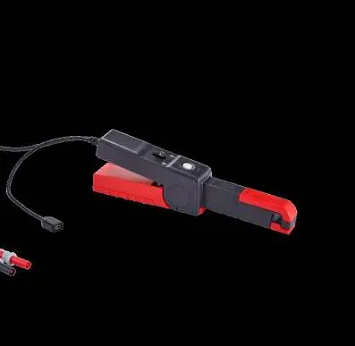
- The manual provides detailed diagrams for each probe model, identifying jaws, opening levers, connectors, and switches.
Model compatibility
- Probes are compatible only with specific AEMC Power Analyzers. Refer to the compatibility table in the specifications section.

Manual page author
Michael Turner
Technical manual editor
Reviews PDF manuals for structure, safety notes, and practical product details so readers can find the right information quickly.