Furniture / Home Furnishing
Installation Guide for Leitner ACS Forged Headbanger
Step-by-step installation guide for the Leitner ACS Forged Headbanger (00-HBA-1823). Includes tool requirements, hardware list, assembly steps, and safety guidelines for your rack system.
Table of contents
Quick guide from the manual
The Leitner ACS Forged Headbanger is an accessory for the Leitner rack system. Installation requires basic knowledge of hand tools and takes approximately 1 hour. Before beginning, ensure you have a clear work area covered with carpet or blankets to prevent scratching the parts. Do not over-tighten bolts; all 8mm bolts must be torqued to 16ft-lb.
Tools required
- Torque wrench
- T40 Torx bit socket
- 13mm wrench
Hardware overview
The kit includes the following hardware:
- M8 x 20 bolts (x6)
- M8 x 14 bolts (x6)
- M8 locknuts (x6)
- Drop-in nuts (x2)
Installation procedure
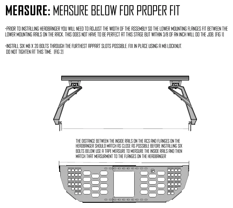
1. Measurement and fitment
Prior to installation, adjust the width of the assembly so the lower mounting flanges fit between the lower mounting rails on the rack. Use a tape measure to ensure the distance between the inside rails on the rack matches the flanges on the Headbanger. Install six M8 x 20 bolts through the furthest apart slots possible and secure with M8 locknuts. Do not fully tighten at this stage.
2. Lower rail fasteners
Install an M8 x 14 bolt and a 1/4 turn Traklok fastener into each lower mounting flange.
3. Preparing the rack
Remove the two screws on the inside of both uprights where the Headbanger will be installed. Depending on your rack's production date, you may need a 5mm Allen wrench or a T40 Torx wrench. If your rack uses 5mm Allen head screws, it is recommended to replace them with the supplied M8 x 14 Torx head screws.
4. Mounting to the rack
Remove any previously installed accessories to facilitate positioning. On both sides of the Headbanger, slide the Traklok bolt into the lower rail. Do not tighten yet.
5. Securing the assembly
Install the four M8 x 14 bolts on both sides of the Headbanger. Fully tighten these bolts first (Step 1), then tighten the Traklok fastener on the lower rail (Step 2). Ensure the Traklok nuts rotate fully into place under the lip of the aluminum extrusion. Finally, tighten all 6 bolts on the Headbanger using a T40 Torx and 13mm wrench.
Use guidelines and safety
- Load Limits: The maximum load is 75 lbs, but this is always subordinate to the vehicle manufacturer's maximum load recommendation. Max truck load = load carrier weight + carrier accessories + weight of the load.
- Maintenance: Periodically inspect all knobs, bolts, screws, straps, and locks for wear, corrosion, and fatigue.
- Operation: Never drive with any lock, knob, or rack in an open or unlocked position.
- Safety: Obey all posted speed limits. High-speed off-road driving can cause damage not covered by warranty.
Warranty
Leitner Designs warrants the product to be free from defects in material and workmanship for two years from the date of purchase. Damage caused by accidents, fire, vandalism, negligence, mis-installation, or misuse is not covered. For warranty issues, contact Leitner Designs customer service at 949-395-3049 or email [email protected].
Practical help
Common problems
Traklok nut not securing properly
Ensure the nut rotates fully into place under the lip of the aluminum extrusion as shown in the diagram.
Rack or accessory damage
Avoid high-speed off-road driving with heavy loads and ensure all bolts are tightened to the specified 16ft-lb.
Fitment issues
Always check the current Fit Guide when obtaining a new vehicle to ensure the rack or accessories are recommended for your specific model.
Before use
- Lay down carpet or blankets to protect parts from scratching.
- Verify you have a torque wrench, T40 Torx bit, and 13mm wrench.
- Measure the distance between the inside rails on the rack and match it to the Headbanger flanges.
- Ensure all hardware (M8 bolts, locknuts, Traklok nuts) is accounted for.
- Check that all locks are turned and moved periodically to ensure smooth operation.
Specs in practice
- Torque Specification
- All 8mm bolts must be tightened to 16ft-lb.
- Installation Time
- Approximately 1 hour.
- Maximum Load
- 75 lbs (subject to vehicle manufacturer's lower limit).
Images and diagrams
- The diagram shows the correct orientation of the Traklok nut. It must rotate fully under the lip of the aluminum extrusion to be secure (Green indicator). Red indicators show incorrect, loose orientations.
Model compatibility
- Always check the current Fit Guide when obtaining a new vehicle.
- The 75 lb load limit is subordinate to the vehicle manufacturer's maximum load recommendation.

Manual page author
Michael Turner
Technical manual editor
Reviews PDF manuals for structure, safety notes, and practical product details so readers can find the right information quickly.