HVAC / Air Conditioners
Installation Manual for LG Sanitary Water Tank Kit PHLTB
Comprehensive installation and configuration guide for the LG Sanitary Water Tank Kit (PHLTB). Includes wiring diagrams, DIP switch settings, and installation steps for HVAC systems.
Quick answers from the manual
Quick answer
- This manual provides installation and configuration instructions for the LG Sanitary Water Tank Kit (PHLTB), including wiring, DIP switch settings, and recirculation pump integration. p. 1
Key actions
- Install Tank p. 1
- Configure DIP Switches p. 1
Problems and fixes
Electric noise
Use shielded wire for signal wire in terminal block 5,6.
p. 1Technical specifications
| Parameter | Value | Meaning | Pages |
|---|---|---|---|
| Heater Wire | > 5mm² | Minimum cross-sectional area for heater wiring. | p. 1 |
Where to find it in the PDF
- Installation and Wiring p. 1
Table of contents
Manual images
Click an image to enlargeQuick guide from the manual
This document provides installation instructions for the LG Sanitary Water Tank Kit (PHLTB). It is intended for authorized personnel only. Always ensure the power is turned off before performing any installation or configuration work to prevent electric shock.
Installation Method
Follow these steps to install the Sanitary Water Tank Kit:
- Uncover: Open the water tank kit and mount it on the wall.
- Power Connection: Connect the water tank kit to the main power supply.
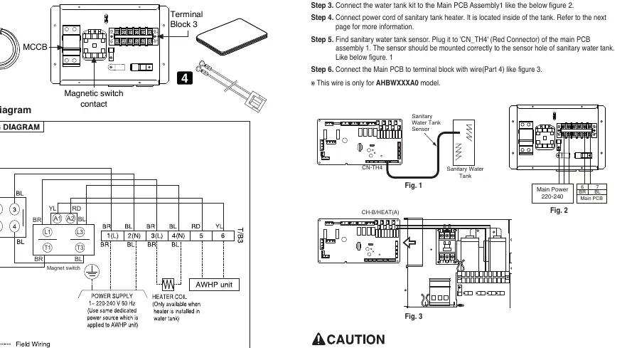
- PCB Connection: Connect the water tank kit to the Main PCB Assembly 1.
- Heater Connection: Connect the power cord of the sanitary tank heater located inside the tank.
- Sensor Installation: Locate the sanitary water tank sensor and plug it into the 'CN_TH4' (Red Connector) of the main PCB. Mount the sensor securely into the sensor socket and bolt it tightly.
- Terminal Connection: Connect the Main PCB to the terminal block using the provided wire (for AHBWXXXA0 model only).
Connecting Sanitary Water Tank
The system requires a 3-way valve (SPDT - Single Pole Double Throw) to manage water flow between the floor heating loop and the sanitary water tank. Ensure the valve is installed according to its specific manual.
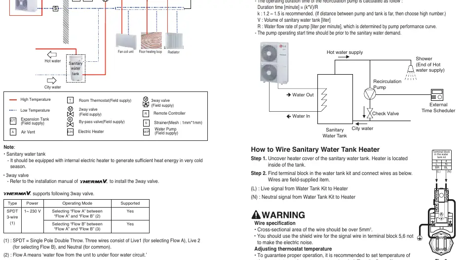
Installing Recirculation Pump
It is strongly recommended to install a recirculation pump to stabilize water temperature and prevent flooding out cold water. The pump should be controlled by an external time scheduler.
Operating duration calculation: Duration [minute] = (k * V) / R
- k: 1.2 ~ 1.5 (recommended). Use a higher number if the distance between the pump and tank is large.
- V: Volume of sanitary water tank [liter].
- R: Water flow rate of pump [liter per minute].
How to Wire Sanitary Water Tank Heater
1. Open the heater cover on the sanitary water tank.
2. Connect the wires to the terminal block in the water tank kit:
- (L): Live signal from Water Tank Kit to Heater.
- (N): Neutral signal from Water Tank Kit to Heater.
Requirements: Use wire with a cross-sectional area over 5mm². Use shielded wire for the signal wire in terminal block 5, 6 to prevent electric noise.
DIP Switch Setting
Turn off the electric power supply before adjusting DIP switches. The settings determine the system configuration:
- Unit only: Switch 2 and 3 OFF.
- Unit + Sanitary water tank: Switch 2 ON, 3 OFF.
- Unit + Sanitary water tank + Solar thermal system: Switch 2 ON, 3 ON.
Manufacturer information
LG Electronics
Practical help
Common problems
Water temperature instability
Install a recirculation pump and configure it with an external time scheduler.
Electric noise in signal wires
Use shielded wire for signal connections in terminal block 5 and 6.
Before use
- Ensure power is turned off before DIP switch adjustment.
- Verify 3-way valve compatibility (SPDT).
- Check wire cross-sectional area (must be over 5mm²).
- Mount sensor tightly in the sensor socket.
- Ensure the installation area is stable and not deteriorating.
Specs in practice
- k (Recirculation factor)
- 1.2 ~ 1.5 recommended factor for calculating pump operating duration.
- Wire specification
- Over 5mm² cross-sectional area required for heater wiring.
Images and diagrams
- Wiring Diagram: Shows connections between MCCB, terminal block, and magnetic switch.
- DIP Switch: Configures the system for Unit only, Unit + Tank, or Unit + Tank + Solar.
Model compatibility
- Requires 3-way valve (SPDT).
- Compatible with specific LG HVAC units.
- Wire (Part 4) is only for AHBWXXXA0 model.

Manual page author
David Miller
Documentation analyst
Organizes user manual content into clear summaries, with attention to model details, product context, and everyday usability.