Tools / Welding Equipment
Operator's Manual for Lincoln Electric BESTER 190C MULTI Welding Machine
Quick guide for the Lincoln Electric BESTER 190C MULTI welding machine. Includes setup, operation modes (GMAW, SMAW, GTAW), maintenance, and troubleshooting steps.
Quick answers from the manual
Quick answer
- The BESTER 190C MULTI is a multi-process welding machine supporting GMAW (MIG/MAG), FCAW-SS, and SMAW (MMA) processes. It requires a 230V single-phase power supply and must be operated by qualified personnel. p. 6, 9, 10
Key actions
- Change welding polarity p. 8
- Load electrode wire p. 8
First start
- Connect power and prepare for welding p. 7, 9
Problems and fixes
Yellow Thermal Indicator is on
Check ventilation, ambient temperature, and duty cycle. It will recover automatically.
p. 12Maintenance and reset
- Routine maintenance p. 11
Technical specifications
| Parameter | Value | Meaning | Pages |
|---|---|---|---|
| Input Voltage | 230V +/- 15% | Single phase supply | p. 3 |
| Weight | 13kg | Net weight | p. 3 |
Where to find it in the PDF
- Technical Specifications p. 3
- Troubleshooting p. 12
Table of contents
Manual images
Click an image to enlargeQuick guide from the manual
The BESTER 190C MULTI is a multi-process welding machine designed for industrial use. It supports GMAW (MIG/MAG), FCAW-SS, and SMAW (MMA) welding processes. Before operation, ensure the machine is connected to a 230V single-phase power supply with an earth pin. The machine requires a generator with at least 30% higher output power than the welder's input power if used off-grid.
Technical Specifications
The machine operates on a 230V (+/- 15%) 50/60Hz supply. It features an IP21S protection class and is designed for operating temperatures between -10°C and +40°C. The duty cycle is based on a 10-minute period; for example, at 60% duty cycle, you can weld for 6 minutes and must break for 4 minutes.
Installation and Setup
- Location: Place the machine on a stable surface with an incline no greater than 15°. Ensure at least 500mm of space around the machine for ventilation.
- Input Connection: Must be connected by a qualified electrician to a socket with an earth pin.
- Polarity: Positive (+) polarity is set at the factory. If changing polarity for specific electrodes or wires, switch off the machine and follow the instructions in the manual.
- Wire Loading: Open the side cover, unscrew the locking nut, and load the wire spool so it rotates anticlockwise. Ensure the spool locating pin fits into the hole. Adjust the pressure roll force to prevent wire deformation or slipping.
Welding Modes
GMAW and FCAW-SS
Connect the gas-cooled gun to the Euro socket. Connect the work lead to the appropriate output socket based on the wire type. Ensure the gas shield is connected if required. Set the welding mode to GMAW using the front panel selector.
SMAW (MMA)
Connect the electrode holder and work lead to the output sockets [8] or [9] according to the required polarity (DC+ or DC-). Set the welding mode to MMA.
GTAW
Requires a separate GTAW torch (not included). Connect the torch to the negative output socket [9] and the work lead to the positive socket [8]. Arc ignition is achieved via the lift TIG method.
Maintenance
Routine (Everyday): Check insulation on all leads, remove spatters from the welding gun nozzle, and ensure the cooling fan airflow slots are clean.
Periodic (Every 200 hours/Year): Clean the machine internally using dry, low-pressure air. Tighten all weld terminals if necessary.
Troubleshooting
If the yellow thermal indicator is on, the machine has exceeded its duty cycle or is overheating; stop welding and allow it to cool. If the wire feeding motor is not working, check for a faulty potentiometer, blocked nozzle, or loose drive roll. If the arc is unstable, check for a worn contact tip, incorrect power cable thickness, or low input voltage.
Practical help
Common problems
Yellow Thermal Indicator is on
Stop welding and allow the machine to cool down. Check for insufficient ventilation or excessive duty cycle usage.
Wire feeding motor not working
Check if the potentiometer is faulty, the nozzle is blocked, or the drive roll tension is too loose.
Arc is not stable and spatter is large
Check for a contact tip that is too large, a power cable that is too thin, or low input voltage.
Arc will not start
Check if the work cable is broken or if the work piece is dirty/rusty/painted.
Before use
- Verify input voltage is 230V.
- Ensure the machine is on a stable surface (max 15° incline).
- Check that the work area has at least 500mm of ventilation space.
- Confirm the correct polarity is set for your welding process (GMAW/SMAW).
- Ensure the wire spool rotates anticlockwise and the pressure roll is adjusted correctly.
Images and diagrams
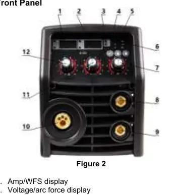
- Front Panel: Contains displays for Amp/WFS and Voltage/Arc Force, mode selection, and wire inching button.
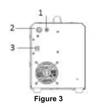
- Rear Panel: Features the gas connector, input power cord, and power switch.
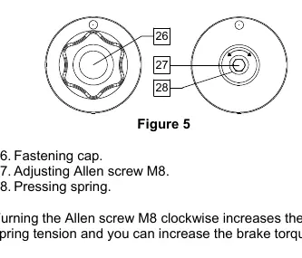
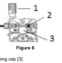
- Wire Loading: Shows the spool, fastening cap, and pressure roll adjustment mechanism.
Model compatibility
- Requires a generator with at least 30% higher output power than the welder's input power.
- Requires a 16A fuse (or higher if welding current I2 > 160A).

Manual page author
Michael Turner
Technical manual editor
Reviews PDF manuals for structure, safety notes, and practical product details so readers can find the right information quickly.