Tools / Welding Equipment
Operator's Manual for Lincoln Electric Pipeliner 200D Kubota
Comprehensive operator's manual for the Lincoln Electric Pipeliner 200D Kubota welder. Includes installation, operation, maintenance, troubleshooting, and wiring diagrams.
Quick answers from the manual
Quick answer
- The Pipeliner 200D Kubota is a diesel engine-driven DC arc welder. It features a Kubota V2403M engine, 200A output at 60% duty cycle, and 1.75kW auxiliary power. p. 8, 9
Key actions
- Starting the engine p. 13
- Purging air from fuel system p. 18
First start
- Check oil, fuel, and battery connections before starting. p. 11, 13
Problems and fixes
Engine does not start
Check fuel, air in system, clogged filter, or glow plugs.
p. 22Error codes
| Code | Meaning | Action | Pages |
|---|---|---|---|
| LONG 1, SHORT 2 | Low oil pressure detected | Check oil level on dipstick. | p. 23 |
| LONG 1, SHORT 4 | High water temperature detected | Check coolant amount/quality. | p. 23 |
Maintenance and reset
- Reset engine protection system by turning ignition switch OFF then ON. p. 9, 13
Technical specifications
| Parameter | Value | Meaning | Pages |
|---|---|---|---|
| Rated Output | 200A @ 28V | Welding output | p. 8 |
| Auxiliary Power | 1.75 kW | 120V DC power | p. 8 |
Where to find it in the PDF
- Installation p. 8, 9, 10, 11
- Operation p. 13, 14, 15
- Maintenance p. 17, 18, 19
- Troubleshooting p. 20, 21, 22, 23
Table of contents
Manual images
Click an image to enlargeQuick guide from the manual
The Pipeliner 200D Kubota is a heavy-duty engine-driven DC arc welding power source. This manual provides essential instructions for safe operation, installation, and maintenance. Always read the safety precautions before attempting to operate or repair the equipment.
Installation
Proper installation is critical for safety and performance:


- Location: Operate with doors closed to maintain designed airflow. Ensure the area is well-ventilated to vent exhaust fumes.
- Grounding: Follow the U.S. National Electrical Code. A grounding stud is provided on the welding generator frame foot.
- Pre-operation Service: Check engine oil level, fuel level, and battery connections. Ensure the water separator valve is open.
Operation
Starting the Engine:
- Turn the Idler switch to HIGH.
- Turn the Ignition switch to ON.
- Press the Glow Plug button for 20 to 30 seconds (maximum 60 seconds).
- Press the Glow Plug button and the Start button simultaneously. Release when the engine starts.
Welder Controls: The control panel includes a Current Range Selector (5 steps) and a Fine Current Adjustment rheostat. Do not adjust the Current Range Selector while welding to avoid damaging the switch.
Maintenance
Regular maintenance ensures longevity:
- Cleaning: Blow out the welder and controls with low-pressure air at least every two months.
- Cooling System: Keep the radiator cap tight. Use a 50-50 mixture of ethylene glycol antifreeze and water.
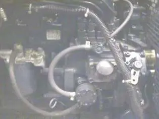
- Fuel System: If the engine runs rough due to air in the fuel system, use the air bleeding valve on the fuel injection pump to purge air.
- Engine Service: Follow the maintenance schedule provided in the manual, including oil changes, filter replacements, and belt inspections.
Troubleshooting
The manual includes detailed guides for:
- Welder Issues: Problems with output, arc stability, or current generation.
- Engine Issues: Starting problems, irregular running, or engine stops.
- Electronic Idler: Troubleshooting the automatic idler system.
- Light Codes: Diagnostic codes for engine protection faults (e.g., low oil pressure, high water temperature).
Practical help
Common problems
Engine does not start
Check for lack of fuel, air in the fuel system, clogged fuel filter, or improper glow plug operation.
Machine fails to hold output consistently
Inspect for a rough/dirty commutator, worn brushes, or loose electrical connections.
Engine stops during operation with protection light on
Refer to the Light Code Diagnoses table in the troubleshooting section to identify the specific fault.
Before use
- Check engine oil level
- Check fuel level
- Ensure air separator valve is open
- Check battery connections
- Ensure proper ventilation
Specs in practice
- Auxiliary Power
- 1.75 kW of 120V DC power available at the control panel receptacle.
Images and diagrams
- Wiring diagrams for codes 11498, 11591, 11644
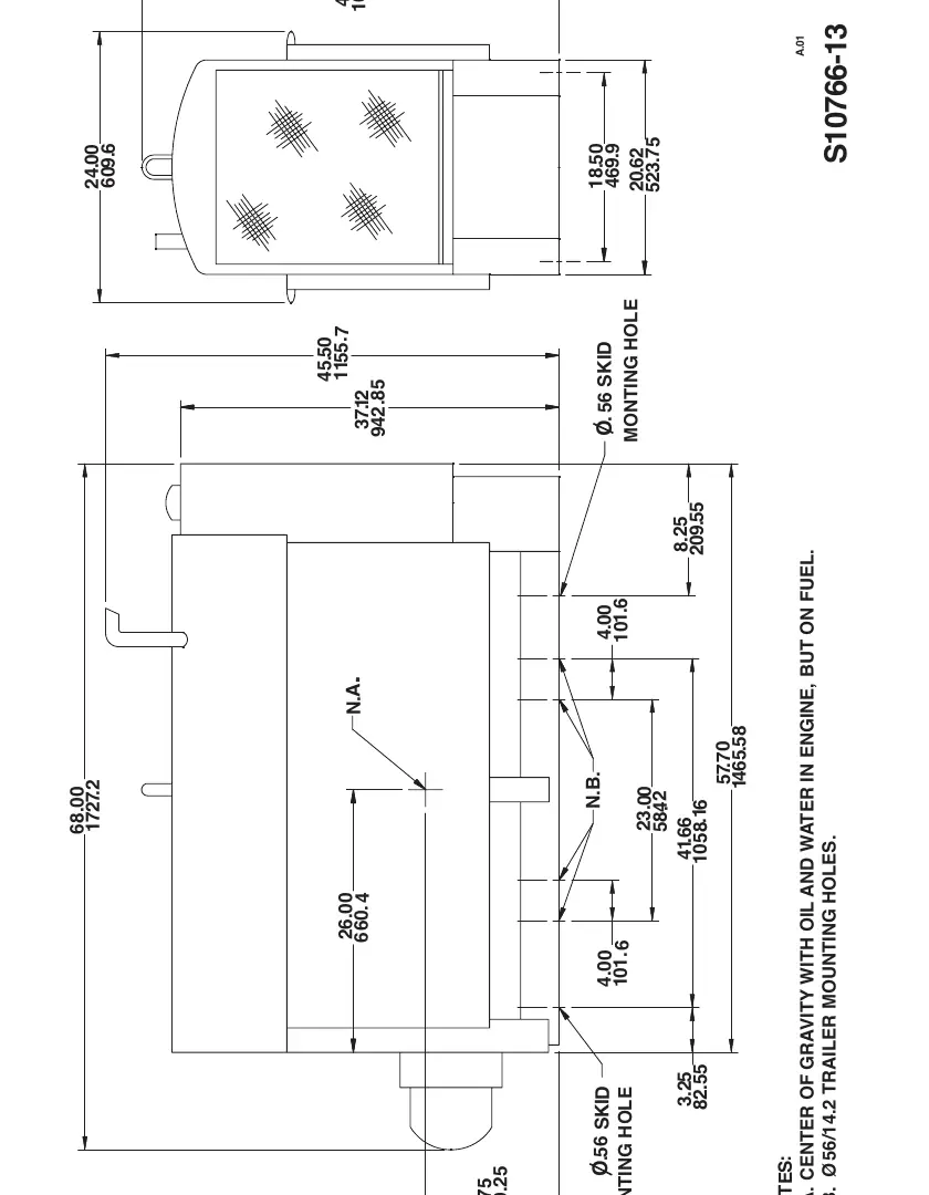
- Dimension print for installation planning
Model compatibility
- Requires low sulfur or ultra-low sulfur diesel fuel in USA/Canada.
- Not for pipe thawing.

Manual page author
Michael Turner
Technical manual editor
Reviews PDF manuals for structure, safety notes, and practical product details so readers can find the right information quickly.