Tools / Measuring Tools
Solinst 415 12V Submersible Pump Operating Instructions
Quick guide for the Solinst 415 12V Submersible Pump. Includes setup, power supply connection, flow adjustment, troubleshooting, and maintenance procedures.
Table of contents
Manual images
Click an image to enlargeQuick Guide to Operation
The Solinst Model 415 12V Submersible Pump is designed for groundwater purging and sampling. Always ensure the pump is fully submerged during operation to prevent motor damage. The controller is water-resistant but not waterproof; do not submerge the controller.
Power Supply and Connection
The pump operates from an external 12V DC power supply (e.g., car, truck, or marine battery) capable of supplying up to 45 amps. The controller features reverse polarity protection; if connected incorrectly, the unit will not operate, but will not be damaged.
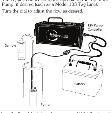
- Red clip: Connect to the positive (+) battery terminal.
- Black clip: Connect to the negative (-) battery terminal.
- Circuit Breaker: If the amperage exceeds 50 amps, the breaker will trip. To reset, turn the dial to 0 and press the reset button on the side of the controller.
Operation and Flow Control
The controller dial adjusts the water flow by varying the voltage output to the pump motor.
- OFF position: 0 volts output.
- 10 position: 25 volts output.
- Flow Adjustment: Turn the dial clockwise to increase flow (faster motor speed) and counter-clockwise to decrease flow.
- Low Voltage Disconnect: The controller will disconnect at 10 volts (indicated by a slowly flashing yellow light) to protect the battery.
Troubleshooting and LED Indicators
If the pump fails to operate, check the following:
- Ensure the pump is submerged and properly connected.
- Verify the battery voltage is at least 12.5V.
- Check the circuit breaker button.
- Ensure the dial is turned to position 10.
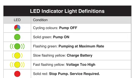
LED Indicator Definitions:
- Cycling colours: Pump OFF.
- Solid green: Pump ON.
- Flashing green: Pumping at Maximum Rate.
- Slow flashing yellow: Charge Battery.
- Fast flashing yellow: Voltage Too High.
- Solid red: Stop Pump. Service Required.
- Slow flashing red: Controller Cool-down Required.
- Fast flashing red: Pump is Disconnected.
Maintenance and Decontamination
Do not run the motor dry, as this will reduce its lifespan. Use the optional disposable filter to prevent sediment from entering the motor.
Decontamination Procedure:
- Unscrew the intake or filter from the bottom of the pump.
- Wash the pump with phosphate-free soap.
- Rinse thoroughly with deionized water and dry.
- Reconnect the intake or a new filter.
Dedicated Well Cap Assembly
For installations using the 2" Dedicated Well Cap Assembly (#116244):
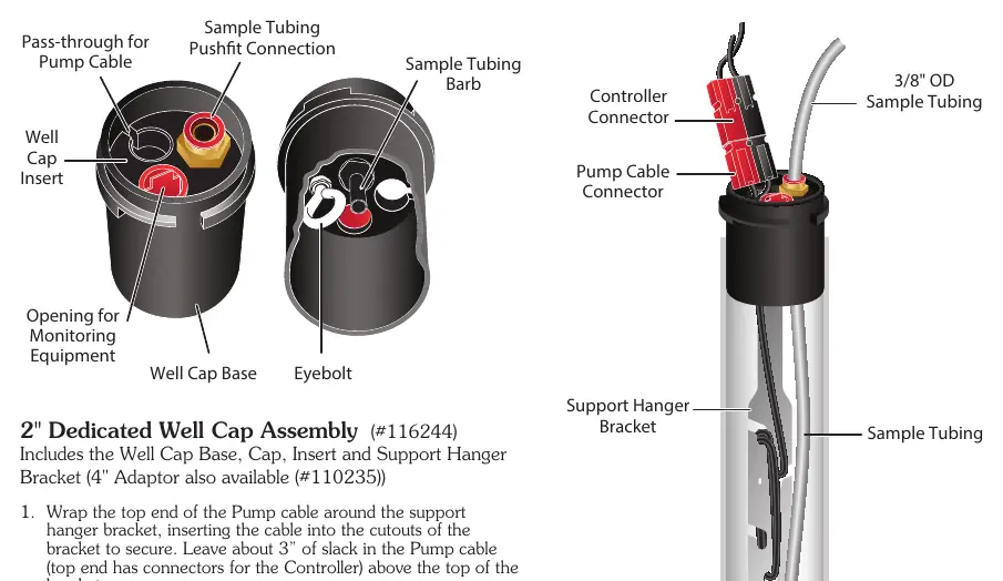
- Secure the pump cable to the support hanger bracket, leaving about 3 inches of slack.
- Pass the cable through the well cap insert.
- Connect the sample tubing to the tubing barb on the bottom of the insert.
- Lower the assembly into the well until the bracket seats on the well cap base.
- Connect the controller to the pump cable connector.
Practical help
Common problems
Pump not working / LED lights off
Check for reverse polarity on battery connections or check if the circuit breaker has tripped.
Low voltage disconnect (slow flashing yellow light)
Battery voltage has dropped below 10V. Stop operation and recharge the battery.
Fast flashing red LED
Indicates an electrical continuity issue. Check all cable connections and voltage.
Controller overheating
Turn the dial to near 0 but keep the unit powered to allow the fan to provide airflow for cooling.
Before use
- Ensure the pump is fully submerged in water.
- Verify 12V DC power source is available (45A capacity).
- Connect red clip to positive (+) and black clip to negative (-) terminal.
- Ensure the controller dial is in the OFF position before connecting power.
- Check that the circuit breaker button is pressed in.
- Ensure tubing is securely pushed onto the tubing barb.
Images and diagrams
- Wiring diagram shows the connection path from the 12V battery to the Pump Controller and the Pump.
- Well Cap Assembly diagram illustrates the routing of the pump cable and sample tubing through the well cap insert.
Model compatibility
- Designed for groundwater purging/sampling only.
- Compatible with 800M Mini Pneumatic Packer.
- Compatible with 2-inch Dedicated Well Cap Assembly (#116244).

Manual page author
David Miller
Documentation analyst
Organizes user manual content into clear summaries, with attention to model details, product context, and everyday usability.