Electronics / Televisions
Matchmaster 04MM-RP04 Recessed Wall Box Installation Guide
Professional installation guide for the Matchmaster 04MM-RP04 recessed wall box, covering new build and existing wall mounting procedures, safety warnings, and technical specifications.
Table of contents
Manual images
Jump to the sectionQuick guide from the manual
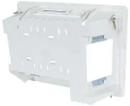
The Matchmaster 04MM-RP04 is a recessed wall box designed for 70mm and 90mm wall cavities. This document provides essential installation procedures for both new construction and existing wall retrofits. Important: Installation must be performed by a licensed electrician or technician. Always turn off power at the circuit breaker or fuse before starting any work.
Safety instructions
- Do not install components during an electrical storm.
- Avoid installation in wet locations unless specifically designed for such use.
- Never touch uninsulated wires or terminals while connected to the network.
- Ensure all power is switched off at the mains before beginning installation.
- If installing multiple recessed points, maintain a minimum distance of 50mm between them (vertically or horizontally).
How to install in new builds
- Select a wall location free from obstructions like timber frames or metal straps.
- Use the provided template to trace and cut the hole in the wall sheeting.
- Slide the power point through the back or side of the RP04 housing.
- Insert the RP04 into the wall and secure it using the preinstalled floating clips in each corner.
- Position power points into the housing and secure them using the 4 x 13mm screws provided.
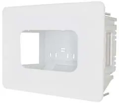
- Clip the RP04 cover into place.
How to install in existing builds
- Unscrew the existing point and check for wall obstructions.
- Push the existing wall point back into the cavity.
- Align the RP04 over the cutout so existing bracket screw holes are visible.
- Mark the top and bottom of the housing and cut the wall sheeting accordingly to expose the existing bracket.
- Remove the old bracket and proceed with the installation steps used for new builds.
Technical specifications
The unit is designed for 70mm and 90mm wall cavities. Screw length used for securing power points must not exceed 25mm. The product is protected by Australian and New Zealand design registrations.
Manufacturer information
Matchmaster Communications Pty Ltd
Practical help
Common problems
Wall sheeting is too hard or tight
Mark the locations of the top and side fins and make small cuts until the plastic shroud fits firmly against the wall.
Existing wall plate is too large or cabling is too tight
Disconnect the cabling from the back of the wall plate and reconnect it through the RP04 housing.
Before use
- Ensure power is turned off at the circuit breaker or fuse.
- Verify the wall cavity depth is suitable (70mm or 90mm).
- Check for internal obstructions like timber frames or metal straps.
- Ensure a minimum 50mm clearance if installing multiple units.
- Confirm you have the provided template and 4 x 13mm screws.
Specs in practice
- Wall cavity depth
- Designed specifically for 70mm and 90mm cavities.
- Screw length limit
- Must not exceed 25mm to prevent damage or protrusion.
Images and diagrams
- The housing features floating clips in each corner for secure mounting.
- Side plates can be knocked out to facilitate cable entry.
Model compatibility
- Designed for use in both new builds and existing wall retrofits.
- Requires professional installation by a licensed electrician.

Manual page author
David Miller
Documentation analyst
Organizes user manual content into clear summaries, with attention to model details, product context, and everyday usability.