Electronics / Antenna Accessories
Installation Guide for Matchmaster 11MM-MT20 Telomast
Comprehensive installation guide for the Matchmaster 11MM-MT20 Telomast. Includes safety warnings, step-by-step assembly instructions, antenna loading specifications, and guying requirements.
Table of contents
Manual images
Click an image to enlargeImportant Safety and Installation Information
The installation of the Matchmaster Telomast should not be undertaken by inexperienced persons. It is strongly recommended that the mast be installed by a suitably qualified tradesperson. Always observe safety precautions, including wearing a builder's hardhat and safety boots. Be extremely cautious of overhead electric cables. Check with local government authorities regarding building approval requirements or Occupational Health & Safety Plans before starting.
Site Selection and Preparation
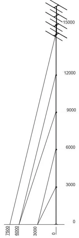
Select the installation site carefully. For level surfaces, refer to the staying diagram for required space. For pitched roofs, special guy lengths and loading conditions apply. Ensure the base and guy anchor points are capable of supporting the design loads. Various foot mount options are available for different surfaces, including the 11MM-TRM-MD (tiled/flat), 11MM-IRM (tin), and 11MM-LARM (flat/sloped).
Installation Procedure
- Base Installation: Securely install the foot mount or base plate to the mast base fixing point. Attach turnbuckles to all guy anchor points. Ensure guy anchors are not located closer to the mast base than specified in the diagram.
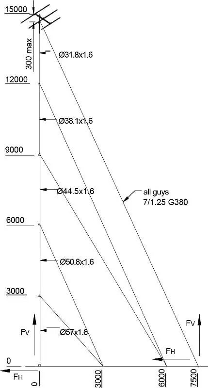
- Mast Preparation: Remove the shipping pin from the bottom of the mast and the small screw from the top lock rings. Slide the top guy support and top guy plate off, then replace them in the opposite order. Screw the lock screws into the lock rings, ensuring they protrude into the top hole of each section (except the top section, which is tightened 300mm below the antenna position). Install thimbles in the guy plates and attach guy wires using three wire rope grips at each end.
- Erection: Stand the mast in the foot mount. Attach the bottom set of guy wires to the turnbuckles. Tighten and verify the mast is vertical using a spirit level.
- Antenna Attachment: Using an elevated work platform, attach the antenna and feeder cable. Line up the guy plates so all fittings face the same direction.
- Extension: Extend the top section until the stop is reached and tighten the lock screw. Extend the next section 80-90mm until retaining pin holes are visible. Clamp with the lock screw, insert the two retaining pins, release the lock screw, and allow the section to drop onto the pins. Turn until notches engage, then retighten the lock screw. Repeat until fully extended.
Guying and Tensioning
Attach guy wires to the correct anchor points without tightening fully. Turn the mast until the antenna provides the best results, then tighten all guy wires evenly to ensure the mast remains straight and vertical. Guy pretension should be 10% of the specified guy minimum breaking force (e.g., 32 kg for 7/1.25 G380 strand). Pretension can be verified using a spring balance. For added security, wire turnbuckles to each other.
Technical Specifications and Loading
The system conforms to relevant Australian Standards (AS 1170.1, AS 1170.2, AS 4055, AS 4100, AS/NZ 4600). The maximum permissible head loading is for wind classifications up to W41, with a maximum antenna Cd * Area of 0.30 m² and a maximum antenna weight of 15 kg. Installers are responsible for ensuring the structure and fixing devices can support the design loads.
Manufacturer information
Matchmaster Communications Pty Ltd
Practical help
Common problems
Mast is not vertical
Tighten guy wires evenly and check for vertical alignment using a spirit level during the installation process.
Risk of over-stressing mast structure
Ensure that guy anchors are located no closer to the mast base than the distances specified in the installation diagram.
Antenna signal performance
Turn the mast until the antenna gives the best results before final tightening of all guy wires.
Before use
- Ensure installation is performed by a qualified tradesperson.
- Wear appropriate safety gear (hardhat, safety boots).
- Check for overhead electric cables.
- Verify the base and guy anchor points can support design loads.
- Obtain necessary building approvals or OHS plans if required.
Specs in practice
- Max antenna weight
- 15 kg maximum load capacity.
- Max antenna Cd * Area
- 0.30 m² maximum projected wind area.
- Guy pretension
- 10% of specified guy minimum breaking force (32 kg for 7/1.25 G380 strand).
Images and diagrams
- Figure 1: Illustrates the 15m Telomast arrangement and required spacing.
- Figure 2: Shows the shipping pin removal process.
- Figure 6: Details the joint and retaining pin mechanism for mast extension.
Model compatibility
- Compatible with 11MM-TRM-MD (tiled/flat), 11MM-IRM (tin), and 11MM-LARM (flat/sloped) foot mounts.

Manual page author
Emily Carter
User documentation editor
Prepares concise manual descriptions and highlights the most useful setup, operation, and maintenance information for readers.