Electronics / Televisions
Matchmaster 03MM-DR3004 VHF TV Antenna Installation Guide
Step-by-step installation guide for the Matchmaster 03MM-DR3004 VHF TV antenna, including element assembly, coaxial cable preparation, connector installation, and mounting instructions.
Table of contents
Manual images
Jump to the sectionQuick guide from the manual
The Matchmaster 03MM-DR3004 is a VHF TV antenna designed for channels 6-12. Proper installation is critical for signal quality. Key steps include swiveling antenna elements into position, correctly stripping the coaxial cable, and ensuring the 'F' connector is installed without damaging the balun circuit board. Always point the shortest elements towards the transmitter for the best reception.
Antenna assembly
- Remove the antenna boom from the carton.
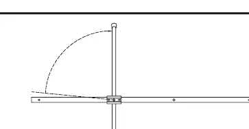
- Swivel all elements 90 degrees until they 'snap lock' into position.
- Attach the long loose element (900mm) to the boom using the hole at the end behind the dipole.
- Attach the short loose element (530mm) to the other end of the antenna boom.
Cable preparation and connector installation
Using the correct cable preparation is essential for a secure connection:
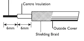
- Strip the coax cable: Remove 6mm of the outer cover and 6mm of the shielding braid as shown in the diagram.
- Install the 'F' connector: Place the connector on the cable and twist to ensure the braid is flat.
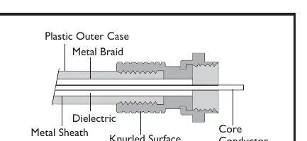
- Insert cable: Push the cable into the rear of the connector and twist clockwise until the dielectric is flush with the bottom nut.
- Verify connection: Ensure 2-3mm of the center core conductor protrudes past the nut and that the braid makes contact with the inner body of the connector.
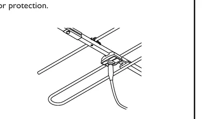
- Connect to balun: Attach the cable to the 'F' connector on the balun. Tighten with fingers only. Warning: Overtightening may damage the circuit board. Slide the boot seal over the connector for protection.
Mounting and alignment
- Assemble the 'U' bolt into the boom.
- Attach the antenna to the mast.
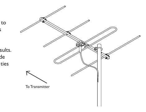
- Point the shortest elements towards the transmitter.
- Rotate the antenna to achieve the best signal results.
- Secure the cable to the mast using UV-grade insulation tape or UV-grade cable ties to support the cable weight and prevent wind damage.
Digital compatibility
For digital reception, terminate the cable into suitable 'F' type splitters (e.g., 07MM-GM02 or 07MM-GM04) or 'F' outlet plates (e.g., 05MM-WP01 or 05MM-WP11). RG6 cable with aluminum foil and aluminum braid is recommended. If located close to the transmitter, use a DA-FLY2M Quad shield flylead to avoid interference.
Manufacturer information
Matchmaster Communications Pty Ltd
Practical help
Common problems
Poor signal reception
Ensure the antenna is rotated so the shortest elements are pointing directly towards the transmitter.
Damaged circuit board
Do not overtighten the 'F' connector on the balun; tighten with fingers only.
Signal interference
If located close to the transmitter, use a DA-FLY2M Quad shield flylead.
Before use
- Ensure all antenna elements are swiveled 90 degrees until they snap lock.
- Verify the long element (900mm) is attached behind the dipole.
- Strip the coax cable correctly (6mm of outer cover, 6mm of shielding braid).
- Ensure 2-3mm of the center core conductor protrudes past the connector nut.
- Use UV-grade tape or cable ties to secure the cable to the mast.
Images and diagrams
- Cable stripping diagram shows 6mm of outer cover removed and 6mm of shielding braid exposed.
- Connector diagram illustrates the dielectric flush with the bottom nut and core conductor protruding.
Model compatibility
- Compatible with RG6 or semi-airspaced cable.
- For vertical polarization, use the 11MM-SM1-15 mount.
- For digital signals, use 'F' type splitters (e.g., 07MM-GM02) or outlet plates (e.g., 05MM-WP01).

Manual page author
Michael Turner
Technical manual editor
Reviews PDF manuals for structure, safety notes, and practical product details so readers can find the right information quickly.