Electronics / Televisions
Matchmaster 03MM-DR3018 VHF TV Antenna Installation Instructions
A complete installation guide for the Matchmaster 03MM-DR3018 VHF TV antenna. Includes step-by-step assembly, coaxial cable preparation, connector installation, and mounting instructions for optimal signal reception.
Table of contents
Manual images
Jump to the sectionQuick guide from the manual
The Matchmaster 03MM-DR3018 is a VHF TV antenna designed for channels 6-12. Installation involves assembling the antenna elements, preparing the coaxial cable with an F-type connector, and mounting the unit to a mast. Ensure you do not overtighten the connector to avoid damaging the circuit board. For best results, point the antenna toward the transmitter.
Antenna Assembly
- Unfold Elements: Swivel the elements on the corner reflector 90 degrees from the packed position until they snap lock.
- Rotate Booms: Rotate the corner reflector booms (located on both sides of the main boom) until they snap lock into position.
- Prepare Elements: Rotate all other elements on both booms to 90 degrees, ensuring they snap lock.
- Attach Dipole: Place the two sections of the antenna together and attach the curved dipole to the underside of the boom at 90 degrees.
Cable Preparation and Connector Installation
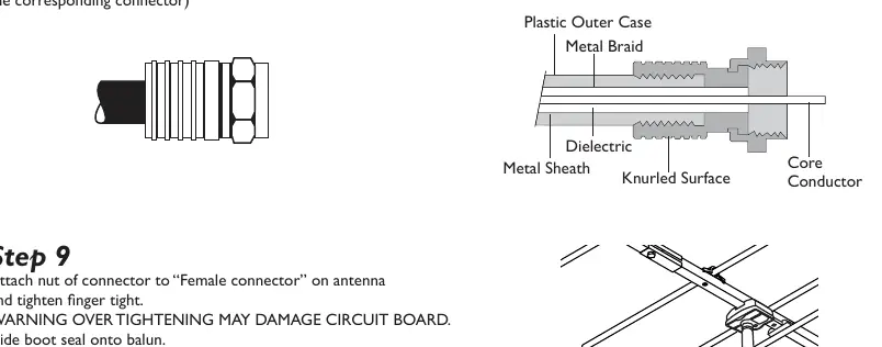
- Prepare Cable: Cut the provided rubber boot seal and slide it onto the cable. Strip the coax cable as shown in the diagram.
- Attach Connector: Select the provided F-connector. Place it on the cable and twist to ensure the braid is flat.
- Secure Connector: Insert the cable into the rear of the connector and twist clockwise until the dielectric is flush with the bottom nut. Ensure 2-3mm of the center core conductor protrudes past the nut.
- Finalize Connection: Attach the nut of the connector to the female connector on the antenna and tighten finger tight. Warning: Over-tightening may damage the circuit board. Slide the boot seal onto the balun.
Mounting and Installation
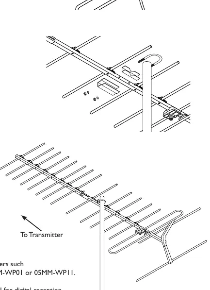
- Assemble U-Bolt: Assemble the U-bolt into the boom.
- Mounting: Attach the antenna to the mast and point it toward the transmitter. Rotate the antenna to achieve the best signal results.
- Cable Management: Attach the cable to the mast using UV-grade insulation tape or UV-grade cable ties to support the cable weight and prevent damage from wind.
Technical Specifications and Compatibility
For digital compatibility, terminate the cable into suitable F-type splitters (e.g., 07MM-GM02, 07MM-GM04) or F-outlet plates (e.g., 05MM-WP01, 05MM-WP11). RG6 cable with aluminum foil and aluminum braid is ideal for digital reception. If you are located close to the transmitter, use a DA-FLY2M Quad shield flylead to avoid interference. In vertical polarized areas, you can use an 11MM-SM1-15 mount (15" vertical stand-off boom, sold separately).
Manufacturer information
Matchmaster Communications Pty Ltd
Practical help
Common problems
Circuit board damage
Do not overtighten the F-connector when attaching it to the antenna; tighten only finger tight.
Signal interference
If located close to the transmitter, use a DA-FLY2M Quad shield flylead to minimize interference.
Cable damage from wind
Secure the cable to the mast using UV-grade insulation tape or UV-grade cable ties to prevent whipping.
Before use
- RG6 coaxial cable (with aluminum foil and braid)
- F-type connectors
- UV-grade insulation tape or cable ties
- Mast for mounting
- 11MM-SM1-15 mount (only if required for vertical polarization)
Images and diagrams
- Steps 1-4 illustrate the unfolding and locking mechanism of the antenna elements and dipole attachment.
- Steps 5-8 detail the precise stripping of the coaxial cable and the correct seating of the F-connector.
- Steps 9-11 show the final connection to the antenna and the mounting procedure on the mast.
Model compatibility
- Compatible with F-type splitters such as 07MM-GM02 or 07MM-GM04.
- Compatible with F-outlet plates such as 05MM-WP01 or 05MM-WP11.
- Vertical polarization requires the 11MM-SM1-15 mount (sold separately).

Manual page author
Emily Carter
User documentation editor
Prepares concise manual descriptions and highlights the most useful setup, operation, and maintenance information for readers.