HVAC / Thermostats & Controls
Installation and Operating Instructions for White Rodgers 1H11G-101 Thermostat
Quick guide for the White Rodgers 1H11G-101 electronic thermostat. Includes installation steps, wiring diagram, operating instructions, and technical specifications.
Quick answers from the manual
Quick answer
- The 1H11G-101 is a non-programmable electronic thermostat for fan coil heating/cooling systems, featuring a 3-speed fan switch and 5°C to 35°C temperature range. p. 1
Key actions
- Install the thermostat on an interior wall, 5 feet above the floor, away from direct heat sources. p. 2
- Set the temperature by pressing the arrow buttons and waiting 15 seconds. p. 2
First start
- Ensure power is disconnected, mount the base, connect wires to the terminal block, and attach the cover. p. 2
Problems and fixes
Wiring uncertainty
If in doubt about whether your wiring is millivolt, line, or low voltage, have it inspected by a qualified contractor.
p. 1Technical specifications
| Parameter | Value | Meaning | Pages |
|---|---|---|---|
| Temperature Range | 5°C to 35°C | Adjustable range for heating/cooling control. | p. 1 |
| Electrical Rating | Up to 12A, 120 VAC | Maximum electrical load capacity. | p. 1 |
Where to find it in the PDF
- Installation and Specifications p. 1
- Wiring and Operation p. 2
Table of contents
Manual images
Click an image to enlargeQuick guide from the manual
The White Rodgers 1H11G-101 is a non-programmable electronic thermostat designed for fan coil heating and cooling systems. It features a manual system switch (Heat-Off-Cool), a three-speed manual fan switch, and an adjustable temperature range of 5°C to 35°C.
Installation
Proper location is essential for accurate temperature control. Follow these guidelines:
- Install the thermostat approximately 5 feet above the floor.
- Mount on an interior partitioning wall, not an outside wall.
- Avoid direct light from lamps, sun, or fireplaces.
- Do not install near windows, doors, air registers, or in areas with poor air circulation.
- Ensure there are no pipes or ductwork in the wall at the chosen location.
Installation Steps:
- Disconnect electrical power at the main fuse or circuit breaker box.
- Remove the thermostat cover by pressing a screwdriver into the slot on top.
- Remove the screw attaching the terminal block cover and remove the cover.
- Mount the base to the wall, pulling wires through the base holes.
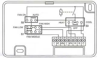
- Connect wires to the terminal block according to the system wiring diagram.
- Replace the front cover, ensuring hooks are locked.
- Turn on the main power switch.
Setting and Operating
To set the desired temperature:
- Press either the up or down arrow button. The LCD will show a flashing temperature with the Heat On and Temperature Set symbols.
- Press the arrow buttons again to adjust to the desired temperature. Each press changes the temperature by 1°C.
- Wait 15 seconds after setting the temperature until the LCD stops flashing. The display will then show the current room temperature, and the unit will control the system to maintain the set point.
Safety Precautions
- Warning: Do not use on circuits exceeding the specified voltage, as this may cause shock or fire hazards.
- Caution: Disconnect power before installation to prevent electrical shock or equipment damage.
- Caution: Setting the thermostat below 5°C may result in damage to the building or contents due to freezing.
Practical help
Common problems
Thermostat not controlling system
Verify wiring against the system wiring diagram (Figure 1). If the system differs, consult a professional electrician.
Display flashing
This is normal when setting the temperature. Wait 15 seconds for the display to stop flashing and confirm the setting.
Before use
- Disconnect electrical power at the main fuse or circuit breaker.
- Verify that the wiring is compatible (millivolt, line, or low voltage).
- Ensure the installation location is 5 feet above the floor on an interior wall.
- Check that the wall location is free of pipes or ductwork.
- Ensure the system switch is in the correct position (Heat/Off/Cool).
Specs in practice
- Temperature Range
- 5°C to 35°C
- Switch Action
- SPST (Heating: open on rise; Cooling: close on rise)
- Electrical Rating
- 6A, 120 VAC (Inductive); 3A, 240 VAC (Inductive); 12A, 120 VAC (Resistive); 6A, 240 VAC (Resistive)
Images and diagrams
- Figure 1 provides terminal identification and wiring hookup instructions.
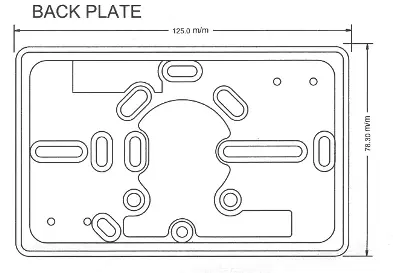
- Figure 3 shows the dimensions and mounting holes for the back plate.
Model compatibility
- Designed for fan coil units in heating/cooling systems.
- Compatible with line voltage valves and/or blower motors.

Manual page author
Michael Turner
Technical manual editor
Reviews PDF manuals for structure, safety notes, and practical product details so readers can find the right information quickly.