Power / Solar Inverters
Quick Installation Guide for Midnite Solar MN 15-12KW-AIO Inverter/Charger System
A comprehensive quick installation guide for the Midnite Solar MN 15-12KW-AIO All-in-One Inverter/Charger System. Includes detailed instructions for mounting, wiring, battery integration, BMS setup, parallel communication, and app...
Table of contents
Manual images
Click an image to enlargeQuick Installation Guide
This document provides essential instructions for the installation and setup of the Midnite Solar MN 15-12KW-AIO All-in-One Inverter/Charger System. Before beginning, ensure all components from the packing list are present and verify that the installation site meets the weight and clearance requirements. The system is rated for both indoor and outdoor installation (NEMA 3R - IP65).
Components and Description
The inverter features several key components for operation:
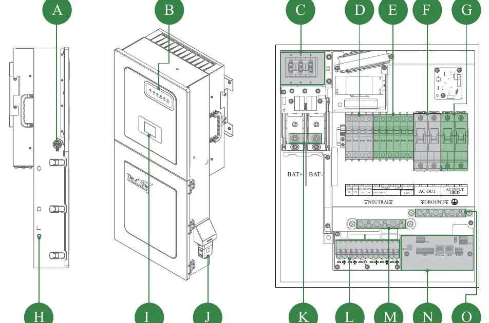
- PV Switch: Disconnects PV input.
- LCD/LED Screens: Provide system status and monitoring.
- Breakers: Includes 300A Battery breaker, 120VAC Load breakers, and Smart Load/Gen input breakers.
- Terminals: Battery connection terminals (5/16-18UNC), PV connection block, and AC Input/Output terminals.
- Communication Ports: Includes RS485, BMS, DRM, CT, DRY, RSD, and PARA ports.
Installation and Mounting
Follow these steps for proper installation:
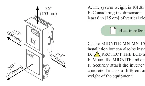
- Location: Ensure the mounting surface can support 101.85 lb (46.2 kg). Provide at least 6 inches of vertical clearance for heat dissipation.
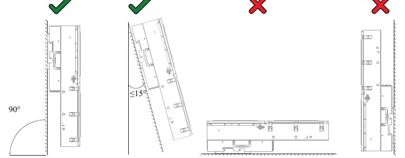
- Orientation: Mount the unit upright or with a lean back of no more than 15°. Do not mount horizontally or upside-down.
- Mounting: Use the provided gutter template to mark the installation location. Secure the inverter to the surface using appropriate anchors.
- Protection: Protect the LCD screen from direct UV exposure.
- Knockouts: Use bushing rings for knockout holes as needed.
Wiring and Connections
All wiring must comply with local electrical codes:
- PV Modules: The inverter has 3 independent MPPTs, each handling up to 2 PV strings (Max Voc 600V).
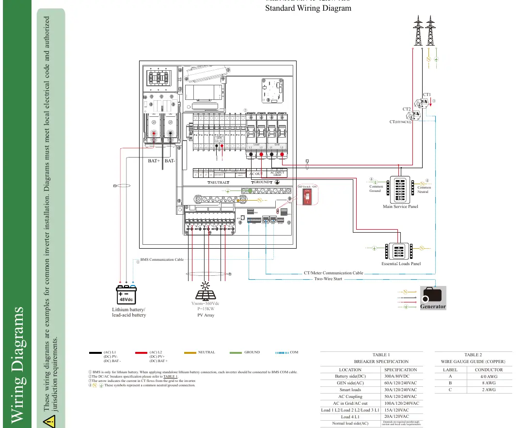
- Batteries: Install the provided battery toroid on battery input wires for EMI suppression. Battery (+) and (-) cables must pass through the toroid simultaneously.
- BMS Port: Used for Lithium battery communication. Ensure correct pinout sequence for the specific battery used.
- CT/Meter: Essential for grid current sensing. Follow the specific wiring diagrams for stand-alone or parallel systems.
- Wi-Fi/Ethernet: Install the dongle by removing the cover and plugging it into the designated port.
Power ON and OFF Sequence
Power ON Sequence:
- Power on the PV.
- Power on the battery (breaker and external switches).
- Power on the AC IN GRID breaker.
- Connect via Bluetooth App and click Power ON, or hold the side ON/OFF button for 5 seconds.
- Power on the AC OUT breaker.
- Power on the SMART LOAD breakers.
- Wait 5 minutes for system checks.
Power OFF Sequence: Reverse the order, starting with AC OUT, then Smart Load, App/Button shutdown, AC IN, Battery, and finally PV. Wait 5 minutes before touching cables.
App Configuration
Download the MidNite Pro App to configure settings:
- Installer Login: Select the installer role to access advanced settings.
- Stored Energy: Configure work modes (Self Consumption, Grid Feed in priority, Off Grid) and battery parameters.
- Communication: Connect to the router via the App.
- Equipment Maintenance: Use this section to synchronize date/time and perform system resets.
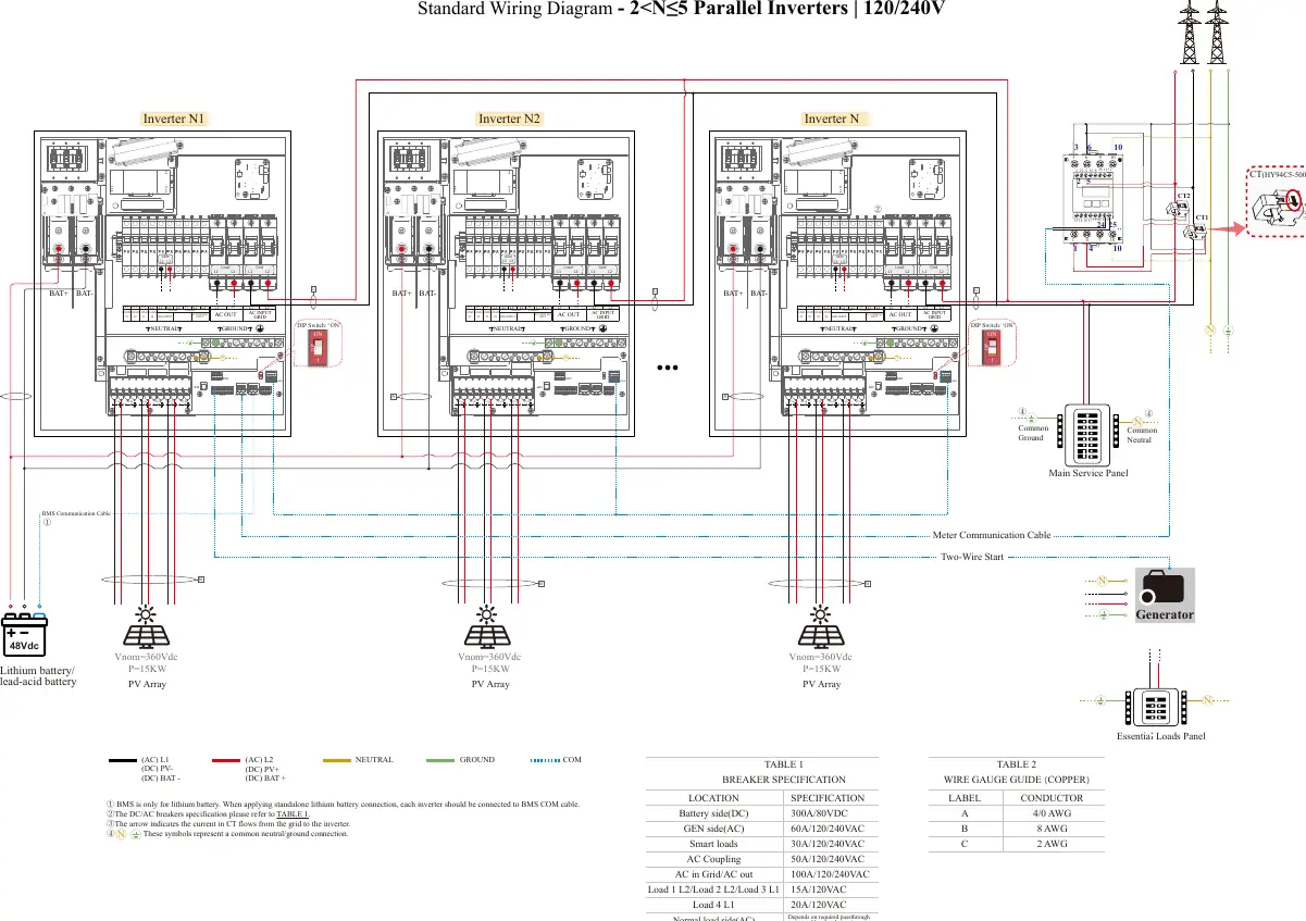
Wiring Diagrams
Refer to the wiring diagrams in the manual for specific configurations, including standard single-inverter setups and parallel configurations (2 to 5 inverters). Ensure all common neutral/ground connections are made according to the diagrams.
Practical help
Common problems
Inverter not starting
Wait 5 minutes after power-on for system checks. Ensure all breakers are in the correct position.
Error identified
Clear the error and wait 5 minutes before restarting.
Communication issues
Check BMS pinout and ensure the matched resistance switch is set to ON for parallel systems.
Before use
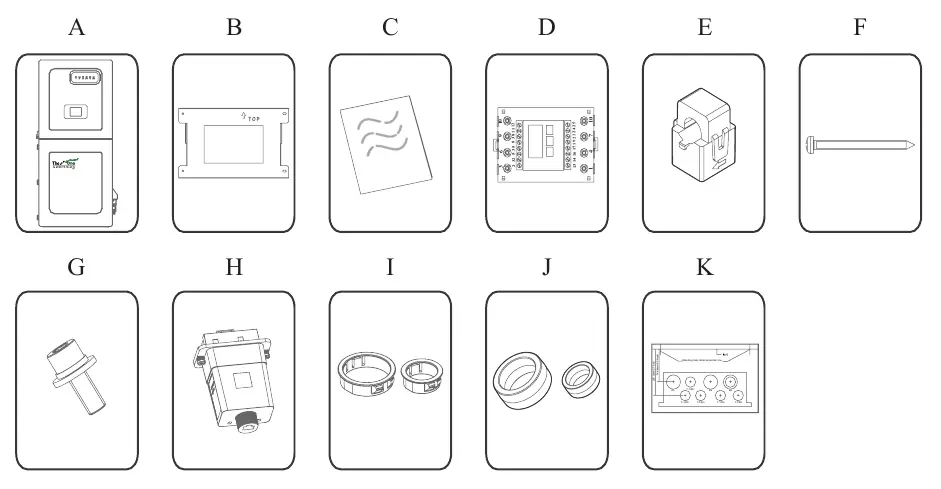
- Verify all items from the packing list are present.
- Ensure mounting surface can support 101.85 lb (46.2 kg).
- Check for at least 6 inches of vertical clearance for heat dissipation.
- Ensure the inverter is mounted upright or with a lean back of ≤15°.
- Verify wire gauges comply with local electrical codes.
- Remove the sticker on the bottom of the equipment before mounting.
Specs in practice
- Inverter Weight
- 101.85 lb (46.2 kg)
- Battery Connection Torque
- 126 in-lb (15 Nm)
- AC Input/Output Max Passthrough
- 100A
Images and diagrams
- Standard Wiring Diagram: Shows connections for PV, Battery, Grid, and Essential Loads.
- Parallel Wiring: Illustrates connections for 2 to 5 inverters in parallel.
- BMS Pinout: Details the pin sequence for RS485 and CAN communication.
Model compatibility
- NEMA 3R - IP65 enclosure rated for outdoor and indoor installation.
- BMS port is for Lithium batteries only.
- Requires MidNite Pro App for local settings.

Manual page author
David Miller
Documentation analyst
Organizes user manual content into clear summaries, with attention to model details, product context, and everyday usability.