Power / Solar Inverters
User Manual for PowMr POW-SunSmart 16KP Hybrid Solar Inverter
Comprehensive user guide for the PowMr POW-SunSmart 16KP hybrid solar inverter. Includes installation, wiring diagrams, operation settings, parallel connection instructions, and troubleshooting.
Quick answers from the manual
Quick answer
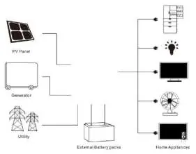
- The PowMr POW-SunSmart 16KP is a hybrid solar inverter that manages power from solar panels, the utility grid, and batteries. It supports split-phase output, parallel operation for up to 6 units, and various battery types. p. 3, 6, 70
Key actions
- Install the inverter on a solid wall at eye level with adequate ventilation. p. 10, 13
- Connect PV, Battery, Grid, and Load cables according to the wiring diagrams. p. 18, 19, 20, 21
- Configure settings via the LCD display menu. p. 28, 31
First start
- 1. Close the battery circuit breaker. 2. Press the ON/OFF switch. 3. Close PV, AC input, and AC output breakers. 4. Start loads from small to large. p. 23
Problems and fixes
No screen display
Check battery/PV circuit breakers and ensure the power switch is ON.
p. 61
Battery under-voltage
Charge the battery until it exceeds the set voltage in parameter [14].
p. 61Error codes
| Code | Meaning | Action | Pages |
|---|---|---|---|
| 01 | Battery undervoltage alarm | Charge the battery. | p. 57, 61 |
| 13 | Bypass overload protection | Reduce load power. | p. 58, 61 |
| 21 | Fan failure | Check for foreign objects. | p. 58, 62 |
Maintenance and reset
- Clean the dust screen periodically. Perform inspections twice a year. p. 13, 65
- To restore factory settings, hold UP and DOWN keys until the time display border flashes, then power off and restart. p. 42
Technical specifications
| Parameter | Value | Meaning | Pages |
|---|---|---|---|
| Rated Output Power | 16000W | Maximum continuous output power. | p. 67 |
| Max. PV Input Power | 12000W + 12000W | Total solar input capacity. | p. 67 |
| Parallel Capacity | 1~6 units | Number of units that can be paralleled. | p. 68 |
Where to find it in the PDF
- Safety Instructions p. 2
- Installation p. 8, 11, 12, 13
- Connection Instructions p. 14, 18, 19, 20
- Operation p. 24, 27, 28
- Fault Codes p. 57, 58, 59, 60
Table of contents
Manual images
Click an image to enlargeQuick guide from the manual
The PowMr POW-SunSmart 16KP is a hybrid solar energy storage inverter designed for industrial scenarios. It integrates solar storage, utility charging, and AC sine wave output. This manual provides essential information for installation, operation, and maintenance. Always ensure installation is performed by a certified technician in compliance with local electrical codes.
Product Overview
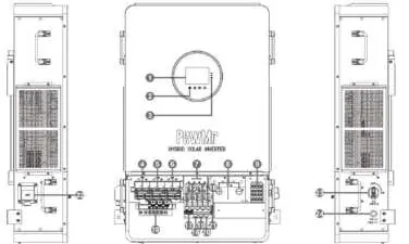
The inverter features a large LCD screen for monitoring system data and status. Key components include grid/generator inputs, load outputs, battery terminals, PV inputs, and various communication ports (CAN, RS485, USB, WiFi, Dry Contact).
Installation
The device is rated IP20 for indoor use. Ensure the mounting location is a solid wall at eye level with adequate heat dissipation space. The ambient temperature should be between -10°C and 55°C (14°F - 131°F).
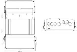
- Mounting: Use the provided wall-mount bracket as a template. Drill holes, insert expansion bolts, and secure the inverter.
- Terminal Cover: Remove the terminal protection cover and anti-insect net using a screwdriver. Clean the dust screen periodically to prevent over-temperature faults.
Connection Instructions
Safety First: Always turn off circuit breakers before making any connections to avoid electric shock.
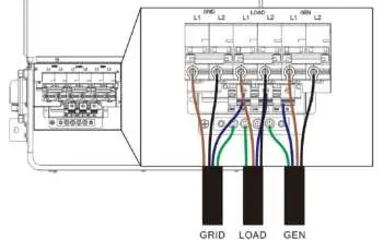
- Grid & Load: Connect live, neutral, and ground cables according to the terminal markings.
- Battery: Connect positive and negative cables using 85mm² / 000 AWG cables with SC95-8 crimp terminals. Ensure correct polarity.
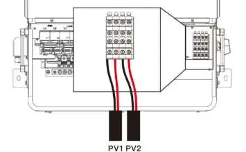
- PV Connection: Ensure the open-circuit voltage of PV modules does not exceed 600V.
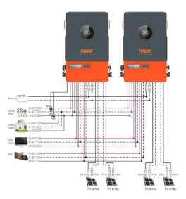
- Parallel Connection: Up to 6 units can be connected in parallel. Use the provided parallel communication cables. Connect PAR-A of one device to PAR-B of the next.
Operation
The display panel includes an LCD screen, LED indicators (AC/INV, CHARGE, FAULT), and 4 operation buttons (Settings, Up, Down, Confirm). Use the settings menu to configure parameters such as AC output mode, battery type, and charging currents.
Maintenance
Perform inspections twice a year:
- Check for blocked airflow and clean the radiator.
- Inspect conductors for damage (sunlight, friction, pests).
- Verify display indications.
- Check terminals for corrosion or high heat and tighten screws.
- Clean the insect screen regularly.
Troubleshooting
The inverter displays fault codes on the LCD screen. Common issues include battery under-voltage, overload, or communication errors. Refer to the fault code table in the manual for specific meanings and solutions. If a fault persists, contact support at [email protected].
Practical help
Common problems
No screen display
Check if the battery or PV circuit breaker is turned on. Ensure the power switch on the bottom is in the 'ON' position.
Battery under-voltage
Charge the battery until the voltage exceeds the value set in parameter [14].
Overload protection
Reduce the load power and restart the device. Refer to protection function item 11.
Fan failure
Turn off the power, check the fan for foreign objects, and clear any blockages.
Before use
- Ensure the installation wall is solid and at eye level.
- Verify ambient temperature is between -10°C and 55°C.
- Check that all cable connections are tight and secure.
- Ensure battery polarity is correct (reversed polarity will damage the inverter).
- Confirm PV open-circuit voltage does not exceed 600V.
- Ensure the terminal protection cover is installed after wiring.
Specs in practice
- Rated Output Power
- 16000W; the maximum continuous power the inverter can supply.
- Max. PV Input Power
- 12000W + 12000W; total solar capacity supported.
- Parallel Capacity
- Up to 6 units can be connected for increased power.
- Protection Degree
- IP20; suitable for indoor use only.
Images and diagrams
- System Connection Diagram: Shows PV, Grid/Generator, Battery, and Load connections.
- Product Overview: Identifies ports 1-24, including inputs, outputs, and communication ports.
- Parallel Wiring: Illustrates how to connect multiple units using parallel communication cables.
Model compatibility
- Supports lead-acid and lithium-ion batteries.
- Compatible with split-phase and three-phase parallel configurations.
- Requires specific communication protocols for BMS integration (e.g., Pylontech, Dyness, etc.).

Manual page author
Michael Turner
Technical manual editor
Reviews PDF manuals for structure, safety notes, and practical product details so readers can find the right information quickly.