Lighting / Fixtures
Installation Instructions for Minka Lavery 2011-66A-L LED Vanity Light
A comprehensive installation guide for the Minka Lavery 2011-66A-L LED Vanity Light. Includes step-by-step mounting instructions, wiring diagrams, and procedures for replacing the LED module.
Quick answers from the manual
Quick answer
- This manual provides installation and LED module replacement instructions for the Minka Lavery 2011-66A-L Vanity Light. p. 1
Key actions
- Mounting the fixture p. 1
- Connecting wires p. 1
First start
- Shut off power at the fuse box or circuit breaker before starting installation. p. 1
Show 4 more answers Show less
Problems and fixes
Replacing LED module
Shut off power, remove fixture body, loosen screws (E), disconnect quick connectors, remove LED module (G), and install new one.
p. 1Maintenance and reset
- The LED module can be replaced by a qualified electrician. p. 1
Technical specifications
| Parameter | Value | Meaning | Pages |
|---|---|---|---|
| Dimming | ELV/LED compatible | Compatible with ELV and/or LED wall dimmer switches. | p. 1 |
Where to find it in the PDF
- Installation and LED Replacement Instructions p. 1
Table of contents
Manual images
Click an image to enlargeQuick guide from the manual
This document provides instructions for the installation and maintenance of the Minka Lavery 2011-66A-L LED Vanity Light. Important: Always shut off power at the fuse box or circuit breaker before beginning any installation or maintenance work. This fixture is compatible with ELV and/or LED wall dimmer switches.
Mounting the fixture
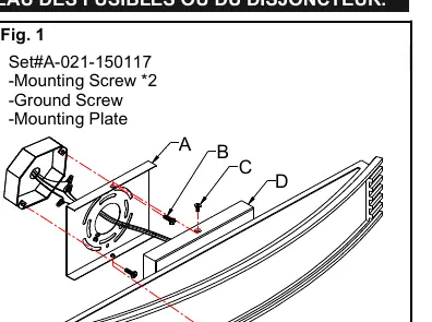
- Shut off power at the fuse box or circuit breaker box and remove the old fixture.
- Unpack the new fixture and organize all parts.
- Loosen screws (C) to remove the mounting plate (A) from the fixture body (D).
- Attach the mounting plate (A) to the junction box (not included) using mounting screws (B). Ensure the side of the mounting plate marked "GND" faces outward.
Connecting the wires
Follow the wiring diagram (Fig. 2) to ensure a safe connection:
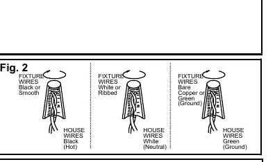
- Connect the fixture's black or smooth wire to the house black (hot) wire.
- Connect the fixture's white or ribbed wire to the house white (neutral) wire.
- Connect the fixture's bare copper or green wire to the house green (ground) wire. If the junction box lacks a ground wire, connect the fixture's ground wire directly to the mounting plate using the provided green screw.
- Tuck all wire connectors neatly into the junction box.
Completing the installation
Place the fixture body (D) over the mounting plate (A) and secure it using the screws (C).
Replacing the LED module
The LED module can be replaced by a qualified electrician without cutting wires or damaging decorative elements:
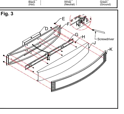
- Shut off the power.
- Remove screws (C) and the fixture body from the mounting plate (A). Disconnect wire connectors and place the body on a clean surface.
- Loosen screws (E) and remove the rectangular plate (K) and acrylic shade (J).
- Press the button marked "L" on the quick connector on the LED module (G) with a screwdriver to disconnect the black wire. Disconnect the white wire marked "N".
- Loosen screws (H) and carefully remove the LED module (G).
- Reverse these steps to install the new LED module.
Practical help
Common problems
Fixture does not light up
Verify that power is turned on at the circuit breaker and check that all wire connections are secure.
LED module needs replacement
Follow the 'Replacing the LED module' section. Ensure power is off before attempting to disconnect the quick connectors.
Before use
- Shut off power at the fuse box or circuit breaker.
- Ensure you have a junction box (not included).
- Verify the mounting plate 'GND' side faces out.
- Check that your wall dimmer is ELV or LED compatible.
Show more Show less
Images and diagrams
- Fig 1: Shows the mounting plate assembly and fixture body attachment.
- Fig 2: Illustrates correct wiring connections for Hot, Neutral, and Ground wires.
- Fig 3: Details the steps for removing and replacing the LED module.
Model compatibility
- Compatible with ELV and/or LED compatible wall dimmer switches.

Manual page author
David Miller
Documentation analyst