Lighting / Fixtures
Installation Instructions for Minka Lavery 2003/2004-77-L Vanity Light
A comprehensive installation guide for the Minka Lavery 2003/2004-77-L vanity light, including step-by-step mounting, wiring instructions, and dimmer compatibility details.
Quick answers from the manual
Quick answer
- This document provides installation instructions for the Minka Lavery 2003/2004-77-L vanity light, covering mounting, wiring, and final assembly. p. 1
Key actions
- Mounting the fixture p. 1
- Connecting wires p. 1
Technical specifications
| Parameter | Value | Meaning | Pages |
|---|---|---|---|
| Dimming | ELV/LED compatible | Compatible with ELV and/or LED wall dimmer switches. | p. 1 |
Show 1 more answers Show less
Where to find it in the PDF
- Installation Instructions p. 1
Table of contents
Manual images
Click an image to enlargeQuick guide from the manual
This document provides the necessary steps to install the Minka Lavery 2003/2004-77-L vanity light. Before starting, ensure the power is shut off at the fuse or circuit breaker box. The fixture is compatible with ELV and/or LED wall dimmer switches.
Mounting the fixture
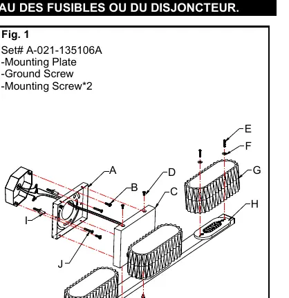
- Shut off power at the fuse box or circuit breaker box and remove the old fixture.
- Loosen screws (D) to remove the mounting plate (A) from the fixture body (C).
- Position the mounting plate (A) on the wall and mark the location for two drywall anchors (I).
- Pre-drill the holes, insert the drywall anchors (I), and attach the mounting plate (A) to the junction box using the provided mounting screws (B). Ensure the side marked "GND" faces out.
- Secure the mounting plate (A) using the woodscrews (J) into the drywall anchors.
Connecting the wires
Follow the wiring diagram carefully to ensure all connections are secure:
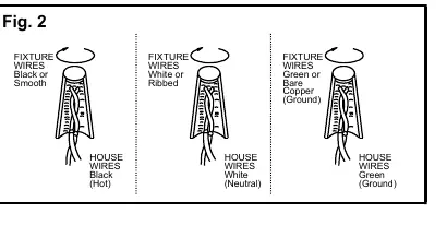
- Black (Hot) wire: Connect to the fixture's black or smooth wire.
- White (Neutral) wire: Connect to the fixture's white or ribbed wire.
- Green (Ground) wire: Connect to the fixture's green or bare copper wire. If the junction box does not have a ground wire, connect the fixture's ground wire directly to the mounting plate (A) using the provided green screw.
After connecting, tuck the wires carefully inside the junction box.
Finishing the installation
- Place the fixture body (C) over the mounting plate (A) and secure it with screws (D).
- Slide screws (E) through the plastic gaskets (F) and glass shade (G), then secure them onto the heat sink (H).
- Return power and test the fixture.
Practical help
Common problems
Fixture does not dim correctly
Ensure you are using an ELV or LED compatible wall dimmer switch.
Before use
- Shut off power at the fuse or circuit breaker box.
- Ensure you have a junction box (not included).
- Verify you have the mounting plate, ground screw, and mounting screws (Set# A-021-135106A).
- Check that you have the necessary tools for drilling drywall anchors.
Show more Show less
Images and diagrams
- Fig. 1 illustrates the mounting plate installation and the assembly of the fixture body and glass shade.
- Fig. 2 provides a wiring diagram showing the correct connections for Hot, Neutral, and Ground wires.
Model compatibility
- Compatible with ELV and/or LED wall dimmer switches.

Manual page author
Michael Turner
Technical manual editor