Lighting / Fixtures
Installation Manual for Minka Lavery 1105-66A 3-Light Pendant
Quick installation guide for the Minka Lavery 1105-66A 3-Light Pendant. Includes step-by-step assembly instructions, wiring diagrams, and bulb specifications.
Quick answers from the manual
Quick answer
- This manual provides instructions for installing the Minka Lavery 1105-66A 3-Light Pendant, including assembly, wiring, and bulb installation. p. 1
Key actions
- Shut off power at the fuse box or circuit breaker. p. 1
- Assemble the fixture by threading rods (F1, F2, F3) and attaching the canopy. p. 1
- Attach the mounting plate (A) to the junction box. p. 1
- Connect the electrical wires (Black to Hot, White to Neutral, Ground to Ground). p. 1
- Install three medium base bulbs (up to 100W each). p. 1
- Secure the glass shade (L) with the plastic washer (M), metal plate (N), and finial (P). p. 1
First start
- Shut off power at the fuse box or circuit breaker box and remove the old fixture. p. 1
Show 2 more answers Show less
Technical specifications
| Parameter | Value | Meaning | Pages |
|---|---|---|---|
| Bulb Type | Medium base | Compatible bulb base type | p. 1 |
| Max Wattage | 100 watts per bulb | Maximum wattage rating per bulb | p. 1 |
| Bulb Quantity | 3 | Number of bulbs required | p. 1 |
Where to find it in the PDF
- Installation Instructions p. 1
Table of contents
Manual images
Click an image to enlargeQuick guide from the manual
Before starting the installation, ensure the power is shut off at the fuse box or circuit breaker. This manual provides instructions for assembling and wiring the Minka Lavery 1105-66A pendant light. Always verify that you have all parts listed in the diagram before beginning.
Preparation
Shut off power at the fuse box or circuit breaker box and remove the old fixture including the mounting hardware. Carefully unpack your new fixture and lay out all the parts in a clean area. Take care not to misplace any small parts necessary for installation.
Assembling the fixture
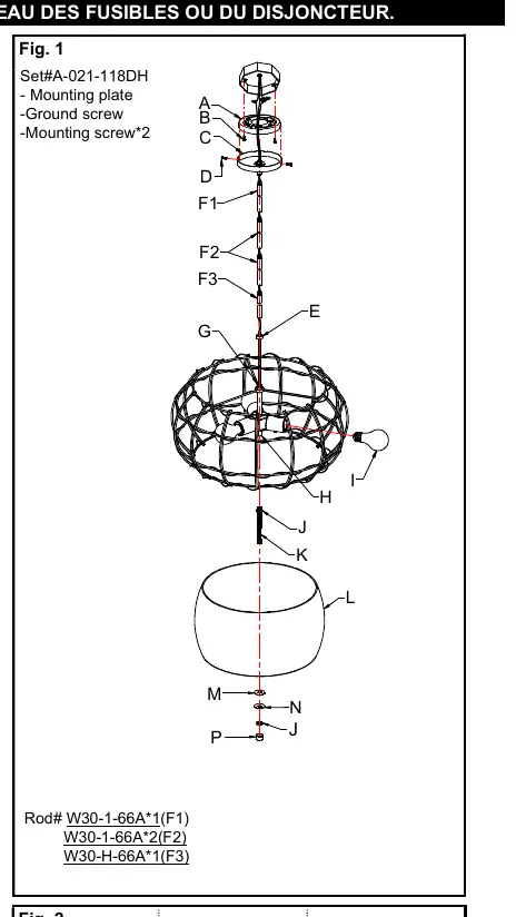
- Place metal cover (E) over all thread (G).
- Determine the desired hanging height and thread rods (F1, F2, and F3) to all thread (G).
- Attach canopy (C) by screwing onto rod (F1). Carefully pass the wires through each rod during assembly.
- Attach mounting plate (A) to the junction box with mounting screws (B). The side of the mounting plate (A) with "GND" marked on it and two convex points must face out.
Connecting the wires
Connect the electrical wires as shown in Fig. 2, making sure that all wire connectors are secured:
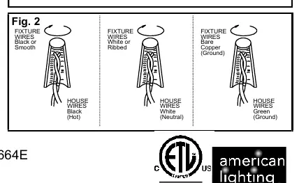
- Black or Smooth fixture wire to Black (Hot) house wire.
- White or Ribbed fixture wire to White (Neutral) house wire.
- Bare Copper fixture wire to Green (Ground) house wire. If your junction box does not have a ground wire, connect the fixture's ground wire directly to the mounting plate (A) using the green screw provided.
Tuck the wire connectors neatly into the junction box.
Completing the installation
- Place canopy (C) over mounting plate (A) and secure with screws (D).
- Thread all thread (K) to coupling (H) and tighten with hex nut (J). Adjust top hex nut position if necessary.
- Install (3) three medium base bulbs (I) up to 100 watts each or CFL or LED equivalent. Do not exceed the maximum wattage rating.
- Place glass shade (L), plastic washer (M), and metal plate (N) through all thread (K). Then secure with hex nut (J).
- Screw finial (P) onto all thread (K) until tight.
Return power to the junction box and test the fixture.
Practical help
Common problems
Fixture does not light up
Check if bulbs are installed correctly and power is restored at the circuit breaker.
Fixture is loose
Ensure the mounting plate is securely attached to the junction box and the canopy screws are tightened.
Before use
- Shut off power at the fuse box or circuit breaker
- Ensure you have all parts listed in Fig. 1
- Verify junction box is compatible
- Check bulb wattage limits
Show more Show less
Images and diagrams
- Fig. 1 shows the assembly order of rods, canopy, and glass shade.
- Fig. 2 illustrates the correct wiring connections for hot, neutral, and ground wires.
Model compatibility
- Compatible with medium base bulbs up to 100W each.
- Requires a junction box for mounting.

Manual page author
Michael Turner
Technical manual editor