HVAC / Parts & Accessories
Installation Instructions for Modine CAS-2B AIRBOOT™ Outside Combustion Air Kit
Step-by-step installation and adjustment guide for the Modine CAS-2B AIRBOOT™ outside combustion air kit. Includes setup for Model POR units with Beckett AF burners, ducting requirements, and maintenance procedures.
Table of contents
Manual images
Click an image to enlargeQuick Guide from the Manual
This document provides installation and adjustment instructions for the Modine CAS-2B AIRBOOT™ outside combustion air kit. This kit is specifically designed for Modine Model POR units featuring a Beckett Model AF burner. Installation must be performed by a qualified installation and service agency. Always ensure the fuel supply is shut off and electrical power is disconnected before starting work.
Kit Components
The kit includes the following parts:
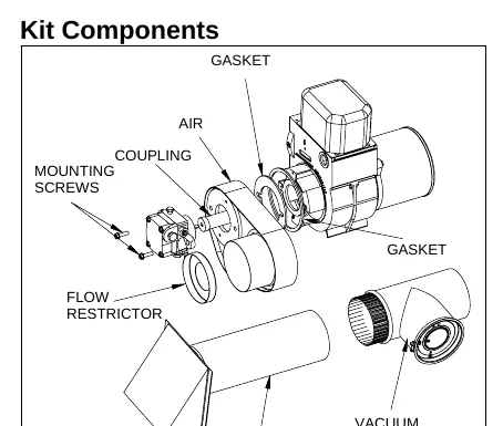
- AIRBOOT™
- Burner Housing Gasket Set
- Mounting Screws (1/4-20 x 1-1/4)
- Extended Coupling
- Flow Restrictor (Note: Not used with Modine model POR units)
- 4" Vacuum Relief Valve (VRV)
- 4" Intake Air Hood (IAH)
AIRBOOT™ Installation
- Remove the fuel pump, air shutter, and air band from the burner housing.
- Remove the original shaft coupling and install the extended coupling (part #21775).
- Install both sealing gaskets to the burner housing.
- Position the AIRBOOT™ over the burner housing on the air intake side.
- Align the holes in the AIRBOOT™ with the housing holes. Guide the pump shaft into the extended coupling and secure the fuel pump with the provided mounting screws. Do not over-tighten.
Note: The AIRBOOT™ can be oriented vertically or horizontally. The spacer ring can be detached by removing the two plastic fasteners, rotating the spacer plate 90 degrees, and reinstalling the fasteners.
Vacuum Relief Valve (VRV) Installation
The VRV provides a secondary opening for combustion air supply in case of blockage. To install:
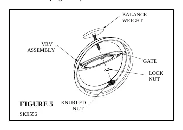
- Mount the VRV tee assembly or 90-degree elbow into the AIRBOOT™ intake using three sheet metal screws.
- Assemble the VRV balance weight onto the gate. Screw the weight all the way in, then attach the lock nut and knurled nut.
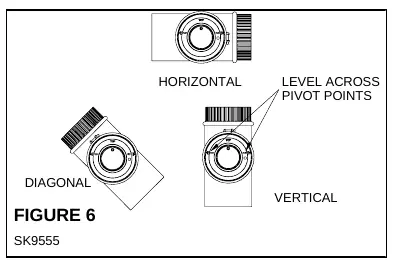
- Mount the VRV assembly into the tee and fasten with the screw and nut in the collar tabs. Ensure the gate is plumb and level across the pivot point.
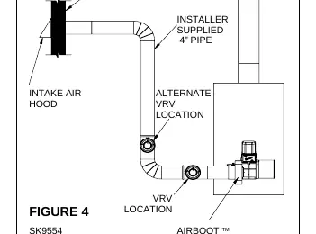
Intake Air Hood and Ducting
- Location: Mount the Intake Air Hood 12 inches above the finish grade (or 12 inches above the snow line in drifting areas).
- Installation: Cut a 4-1/4" diameter hole through the side wall. Slide the hood through and fasten to the wall. Seal the edges with silicone sealant. Always mount with the opening pointing down.
- Ducting: Do not exceed a maximum of 34 total equivalent feet (20' straight pipe + two 90-degree elbows). Route ducting from the VRV tee to the Intake Air Hood using minimal elbows. Support the duct work to prevent damage.
- Cold Climates: Insulate the duct work at least 10 feet from the Intake Air Hood to prevent sweating if operating in temperatures of -10°F or below.
Burner Start-Up and Adjustment
After installation, perform the initial startup and adjustment:
- Set the initial AIRBOOT™ air dial setting based on the model size (100, 145, or 185).
- Allow at least ten minutes for warm-up.
- Perform a smoke test. Adjust the air dial until a trace of smoke is obtained.
- Measure CO2 in the flue gas at the trace of smoke level. Open the air dial to add reserve air until CO2 is lowered to 11.5% - 12.5%.
- Perform a smoke test again to ensure the paper is clean (zero smoke).
- Tighten the lock screw on the air dial after final adjustments.
Maintenance
During annual servicing, inspect the Inlet Air Hood and air supply system for foreign material, especially the 1/4" mesh screen. Verify the VRV is operating properly and re-verify the smoke level is at "zero smoke".
Practical help
Common problems
Duct sweating in cold weather
Insulate the duct work at least 10 feet from the Intake Air Hood if operating in temperatures of -10°F or below.
Excessive smoke during start-up
Adjust the AIRBOOT™ air dial to add more air until the smoke level is reduced to zero.
Inadequate combustion air
Check the Intake Air Hood and air supply system for accumulation of foreign material, particularly the 1/4" mesh screen.
Before use
- Ensure fuel supply is shut off.
- Disconnect electrical power.
- Verify compatibility with Modine Model POR units and Beckett Model AF burners.
- Ensure the Intake Air Hood is mounted 12 inches above grade or snow line.
- Check that the duct length does not exceed 34 total equivalent feet.
Specs in practice
- Maximum Duct Length
- 34 total equivalent feet (20' straight pipe + two 90-degree elbows).
- Over-fire Draft
- Should be -.02" W.C. when burner air supply and draft are properly adjusted.
Images and diagrams
- Figure 1: Exploded view of kit components including AIRBOOT, gaskets, and VRV.
- Figure 2: Shows vertical and horizontal orientation options for the AIRBOOT.
- Figure 4: Illustrates the installation of the VRV tee assembly.
- Figure 6: Shows the correct leveling of the VRV gate across pivot points.
Model compatibility
- Specifically designed for Modine Model POR units with Beckett Model AF burners.
- Flow Restrictor included in the kit is NOT used with Modine model POR units.

Manual page author
Emily Carter
User documentation editor
Prepares concise manual descriptions and highlights the most useful setup, operation, and maintenance information for readers.