Toys / Model Accessories
mXion PWD 2-Channel Function Decoder User Manual
A comprehensive user guide for the mXion PWD 2-channel function decoder. This manual covers installation, wiring diagrams, CV programming, technical specifications, and troubleshooting for your model railway lighting control.
Quick answers from the manual
Quick answer
- The mXion PWD is a 2-channel function decoder for model trains, providing lighting control, effects, and power buffering. It supports DC, AC, and DCC operation. p. 5, 9
Key actions
- Reset the decoder p. 13
- Unlock programming p. 11
Problems and fixes
Accidental programming
Use CV 15/16 to lock the decoder.
p. 11Maintenance and reset
- Reset via CV 7 p. 13
Technical specifications
| Parameter | Value | Meaning | Pages |
|---|---|---|---|
| Voltage | 7-27V DC/DCC, 5-18V AC | Operating voltage range | p. 22 |
| Max Current | 1A per channel | Maximum load per output | p. 22 |
Where to find it in the PDF
- Connectors p. 8
- CV Table p. 16, 19
Table of contents
Manual images
Click an image to enlargeQuick guide from the manual
The mXion PWD is a 2-channel function decoder designed for model trains, particularly suitable for LGB cars with factory lighting. It supports DC, AC, and DCC operation. Key features include a built-in buffer for up to 3 minutes of power, a 5V generator, and support for various lighting effects. Always ensure the output voltage matches your consumers to prevent damage.
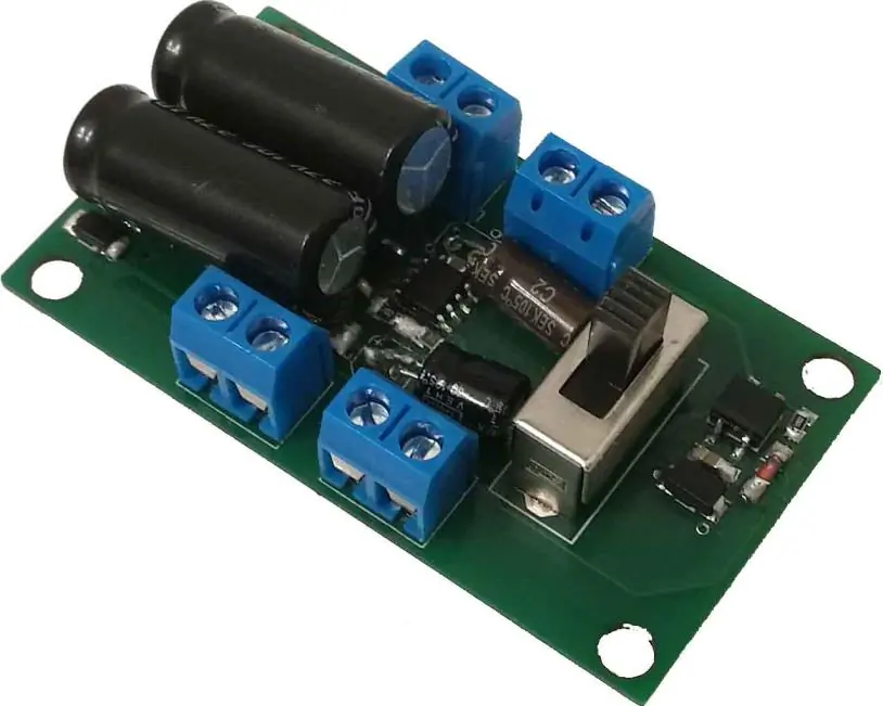
Product description
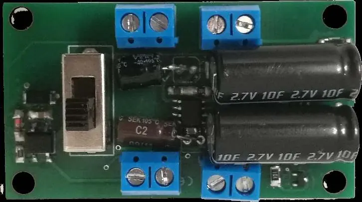
The PWD is a compact decoder that can replace existing electronics in model cars. It features two reinforced function outputs, each capable of handling up to 1 Amp. It supports digital and analog modes, with full functionality available in both. The module includes a switch for the buffer and supports advanced lighting effects like dimming, random control, and strobe lights.
Installation and wiring
Install the device in a protected location, ensuring it is not exposed to moisture. Avoid short circuits by ensuring no metal parts touch the mounting screws or the board. Connect your consumers to the A1 and A2 terminals. The track inputs are clearly marked on the board. The connection can be made via screw terminals or by soldering.
Programming
The decoder is programmed via CV (Configuration Variables). To prevent accidental programming, use the programming lock (CV 15/16). Only when CV 15 = CV 16 is programming possible. The decoder supports bitwise, POM (Programming on Main), and register programming. You can reset the decoder using CV 7 by writing specific values: 11 for basic functions, 16 for the programming lock, and 33 for function outputs.
Technical data
- Voltage: 7-27V DC/DCC, 5-18V AC
- Current consumption: 5mA (without function outputs)
- Max function current: 1A per channel (A1, A2)
- Max total current: 1A
- Temperature range: -20 to 65°C
- Dimensions: 2 x 1.5 x 0.5 cm
Practical help
Common problems
Device not responding to programming
Check the programming lock. Ensure CV 15 equals CV 16 to enable programming.
Device destroyed after connection
Ensure output voltages are set to the appropriate value for your consumers before connecting.
Short circuit during installation
Ensure no metal parts or mounting screws are causing a short circuit on the board.
Before use
- Ensure the device is installed in a protected, dry location.
- Verify that output voltages match your consumers.
- Check for short circuits before powering on.
- Ensure the latest firmware is installed if specific features are required.
Specs in practice
- Max function current
- 1A per channel (A1 and A2) is the maximum load the output can handle.
Images and diagrams
- Connect track inputs to the designated terminals on the board.
- Connect lighting consumers to terminals A1 and A2.
Model compatibility
- Compatible with NMRA-DCC.
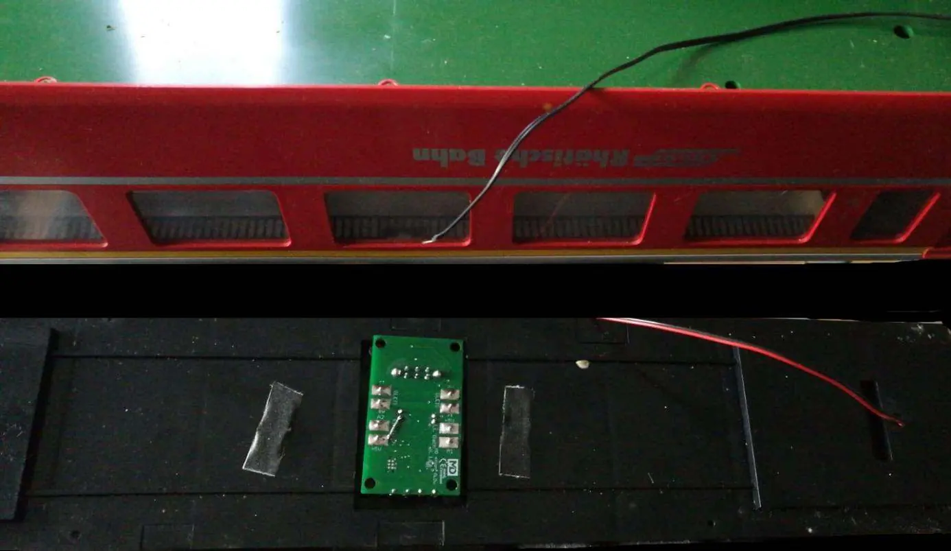
- Ideal for LGB cars with factory lighting (e.g., DB cars, RhB cars).

Manual page author
Michael Turner
Technical manual editor
Reviews PDF manuals for structure, safety notes, and practical product details so readers can find the right information quickly.