Power / Batteries & Chargers
Type S LM534402 2-Light Wiring Harness
Quick guide for the Type S LM534402 2-Light Wiring Harness. Includes installation steps, wiring diagrams, remote control operation, and technical specifications.
Quick answers from the manual
Quick answer
- The LM534402 is a 2-light wiring harness with wireless remote control, designed for 12V DC automotive lighting systems. It includes a 15A in-line fuse and supports two-channel operation. p. 1
Key actions
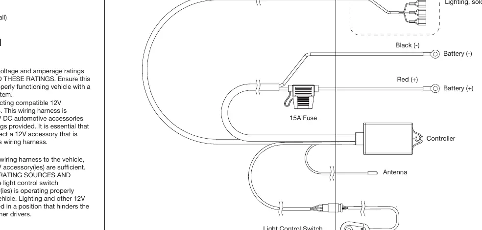
- Connect positive wires to RED/WHITE spade terminals and negative wires to the BLACK spade terminal. p. 1
First start
- Test fit the harness, connect to 12V power, test functionality, then route and mount the switch. p. 1
Problems and fixes
Electrical issues or failure to operate
Check the 15A in-line fuse and ensure all connections are secure and not damaged.
p. 1Maintenance and reset
- Disconnect the Wiring Harness before attempting any maintenance or cleaning. p. 1
Technical specifications
| Parameter | Value | Meaning | Pages |
|---|---|---|---|
| Voltage | 12V DC | Operating voltage | p. 1 |
| Fuse | 15A | In-line fuse rating | p. 1 |
Where to find it in the PDF
- Installation and Operation Guide p. 1
Table of contents
Quick guide from the manual
The Type S LM534402 is a 2-light wiring harness designed for 12V DC automotive lighting. It features wireless remote control operation and a 15A in-line fuse. Before installation, ensure your vehicle's electrical system is functioning properly and that you have the necessary tools, such as a crimp tool, electrical tape, and cable ties.
Package Includes
- 1 x 2-Light Wiring Harness (In-line Switch and 15A Fuse)
- 1 x Keychain Remote Control
- 6 x Spade Terminals (Connectors and Sleeves)
Installation
Preparation:
- Draw a diagram of your intended light, switch, and controller placement to determine wire length requirements.
- Test fit the harness with the engine cool to ensure wires reach the lights.
- Ensure the light control switch functionality is tested before permanent mounting.
Wiring Steps:
- Connect the lights to the output sets.
- For two lights on one output: Insert the positive (+) wire from the first light into the RED (+) spade terminal and the second light into the WHITE (+) spade terminal. Connect both negative (-) wires to the BLACK (-) spade terminal.
- Use a crimp tool to secure all wires.
- Test light functionality before securing the switch and controller.
- Route the switch and controller inside the vehicle interior, typically through a firewall grommet.
- Mount the switch and secure loose wires using cable ties and wire loom.
Controlling Your Lights
The included keychain remote allows for wireless operation:
- ON Button: Press once to activate channel 1, press again for channel 2, and press a third time to activate both channels.
- OFF Button: Turns off all channels. The harness will resume the last used mode when turned back on.
- Slow Strobe Button: Enables slow strobe mode.
- Fast Strobe Button: Enables fast strobe mode.
Specifications
- Voltage: 12V DC
- Fuse: 15A In-Line
- Remote Battery: 3V DC CR2032
- Light Control Switch to Controller: 112.2 inches / 2.85m
- Spade Terminals to Controller: 137.8 inches / 3.5m
- Ring Terminals to Controller: 19.69 inches / 0.5m
Safety and Warnings
- Do not exceed the voltage and amperage ratings.
- Keep wires away from heat-generating sources and moving parts.
- Do not install in a position that hinders the driver's visibility.
- Disconnect the harness before maintenance or cleaning.
- Do not disassemble the wiring harness.
Practical help
Common problems
Lights do not turn on
Check the 15A in-line fuse, verify the 12V power connection, and ensure the remote battery (CR2032) is charged.
Remote not responding
Ensure the controller is properly powered and the remote battery is installed correctly.
Before use
- Verify 12V DC power source availability.
- Ensure wiring harness is free from damage.
- Gather crimp tool, electrical tape, and cable ties.
- Identify a grommet on the firewall for interior routing.
- Test light functionality before permanent mounting.
Specs in practice
- Remote Battery
- 3V DC CR2032 coin cell.
Images and diagrams
- The wiring diagram illustrates the connection of the controller to the battery (Red/Black), the antenna, and the light control switch.
- It shows how to connect two lights to the output sets using the provided spade terminals.
Model compatibility
- Compatible with 12V DC automotive accessories.
- Designed for use with TYPE S Off-Road Lighting (sold separately).

Manual page author
Michael Turner
Technical manual editor
Reviews PDF manuals for structure, safety notes, and practical product details so readers can find the right information quickly.