Lighting / Industrial Lighting
Installation Instructions for LED Linear High Bay
A comprehensive installation and wiring guide for the LED Linear High Bay. Includes step-by-step instructions for chain, cable, and pendent mounting, 0-10V dimming wiring diagrams, and field-adjustable color temperature (CCT) settings.
Quick answers from the manual
Quick answer
- The LED Linear High Bay is installed by mounting it via chain, cable, or pendent hardware, followed by standard 120-277V wiring. If using 0-10V dimming, connect the purple and pink/gray wires; otherwise, cap them off. Color temperature can be adjusted via a switch on the driver box. p. 1, 2
Key actions
- Mounting the fixture p. 1, 2
- Wiring the fixture p. 1
- Adjusting Color Temperature p. 2
Problems and fixes
Improper fixture operation
Ensure 0-10V dimming leads are capped separately if not in use.
p. 1Where to find it in the PDF
- Installation and Wiring p. 1
- Mounting Options and CCT Adjustment p. 2
Table of contents
Manual images
Click an image to enlargeImportant Information
This document provides installation and wiring instructions for the LED Linear High Bay. Warning: Installation, service, and maintenance should be performed by a qualified licensed electrician. Always disconnect electrical power at the fuse or circuit breaker box before beginning any work.
Installation
The fixture supports multiple mounting methods. Ensure all hardware is rated for the load.
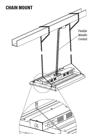
- Chain Mount: Install the chain into the provided wire hanger. Secure the other end to a structure. Install the wire hanger on the side of the top LED channel, ensuring it is fully engaged in the side holes.
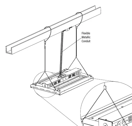
- Cable Mount: Follow the specific cable mounting hardware instructions provided with the optional cable kit.
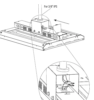
- Pendent Mount: Use the appropriate pendent mounting hardware (e.g., 3/8" IPS) to secure the fixture to the structure.
Wiring
Ensure supply voltage is correct by comparing it with the luminaire label. All connections must be made in accordance with the National Electrical Code.
- Standard Wiring: Connect Black to Hot, White to Neutral, and Green to Ground.
- 0-10V Dimming: The driver compartment contains Purple (Dim+) and Pink/Gray (Dim-) wires. Connect these only to 0-10V low voltage dimming wiring. If not using a dimming circuit, ensure these leads are capped separately to prevent improper operation and voiding the warranty.
Color Temperature Adjustment
The fixture features Tone-Select technology for field-adjustable color temperature.
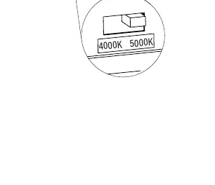
- Locate the slide switch on the side of the driver box.
- Slide the switch to the desired position to select between 4000K or 5000K.
Maintenance
Clean all residues and fingerprints from the fixture and lens after installation. Double-check all hanging hardware before completing the installation.
Practical help
Common problems
Improper fixture operation or voided warranty
Ensure 0-10V dimming leads (Purple/Pink/Gray) are capped separately if not connected to a dimming circuit.
Wiring damage or abrasion
Do not expose wiring to edges of sheet metal or other sharp objects during installation.
Before use
- Disconnect electrical power at the circuit breaker.
- Verify supply voltage matches the luminaire label.
- Ensure all wiring connections are capped with UL approved wire connectors.
- Confirm mounting hardware is rated for the fixture load.
- Ensure the green ground screw is in the proper location and not relocated.
Images and diagrams
- The wiring diagram shows the connection for line voltage (Black/White/Green) and the separate 0-10V dimming control circuit.
- Mounting diagrams illustrate the attachment points for chain, cable, and pendent configurations.
- The CCT switch diagram shows the location on the driver box side for selecting 4000K or 5000K.
Model compatibility
- Suitable for Dry or Damp locations.
- Requires minimum 90°C supply conductors.

Manual page author
Michael Turner
Technical manual editor
Reviews PDF manuals for structure, safety notes, and practical product details so readers can find the right information quickly.