Lighting / Industrial Lighting
Installation Instructions for Superior Life LED Linear High Bay
A comprehensive installation guide for the Superior Life LED Linear High Bay. Includes step-by-step instructions for chain, cable, and pendent mounting, detailed wiring diagrams, and safety precautions for 120-277V systems.
Quick answers from the manual
Quick answer
- The LED Linear High Bay is installed by mounting it via chain, cable, or pendent methods and wiring it to a 120-277V source. Ensure a qualified electrician performs the work and that 0-10V dimming wires are capped if not in use. p. 1, 2
Key actions
- Disconnect power before installation or servicing. p. 1
- Cap unused dimming wires. p. 1
Problems and fixes
Improper fixture operation
Ensure dimming leads are capped off separately if not connected to a 0-10V dimming circuit.
p. 1Maintenance and reset
- Clean residues/fingerprints from the fixture and lens. p. 1
Technical specifications
| Parameter | Value | Meaning | Pages |
|---|---|---|---|
| Voltage | 120-277V | Input voltage range | p. 1 |
| Dimming | 0-10V | Low voltage dimming control | p. 1 |
Where to find it in the PDF
- Installation and Wiring p. 1
- Additional Mounting Options p. 2
Table of contents
Manual images
Click an image to enlargeQuick guide from the manual
This document provides installation instructions for the Superior Life LED Linear High Bay (120-277V). Important: Installation, service, and maintenance must be performed by a qualified licensed electrician. Always disconnect electrical power at the fuse or circuit breaker box before beginning any work.
Installation preparation
- Inspect the new LED fixture for any damages upon removal from packaging.
- Handle the fixture with care.
- Verify that the supply voltage matches the luminaire label information.
- Ensure all wiring connections are capped with UL-approved wire connectors.
- Do not expose wiring to edges of sheet metal or sharp objects.
Mounting options
Standard chain mount
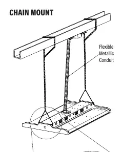
- Install the chain into the provided wire hanger.
- Secure the other end of the chain to a structure rated for the load.
- Install the wire hanger on the side of the top LED channel, ensuring it is fully engaged into the side holes.
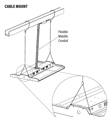
Cable mount
Follow the specific cable mounting configuration provided in the manual, ensuring the flexible metallic conduit is properly routed and secured.
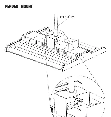
Pendent mount
Use the designated pendent mount hardware (for 3/8 inch IPS) to secure the fixture to the ceiling structure.
Wiring instructions
Connect the LED high bay wiring to the line voltage wire:
- Black: Hot
- White: Neutral
- Green: Ground
Dimming wiring (0-10V):
- The purple and pink (or gray) wires inside the driver compartment are for 0-10V low voltage dimming.
- Connect these only to dimming low voltage wiring.
- If not using a 0-10V dimming circuit, ensure these leads are capped off separately. Failure to do so may cause improper fixture operation and void the warranty.
Maintenance
- Clean all residues and fingerprints from the fixture and lens after installation.
- Double-check all hanging hardware before completing the installation.
- Always turn off power before performing any maintenance.
Practical help
Common problems
Improper fixture operation or voided warranty
Ensure 0-10V dimming leads (purple and pink/gray) are capped off separately if not connected to a dimming circuit.
Risk of electrical shock or fire
Ensure power is disconnected at the circuit breaker before installation or maintenance and verify supply voltage matches the label.
Before use
- Turn off electrical power at the fuse or circuit breaker box.
- Verify supply voltage matches the luminaire label.
- Ensure a qualified licensed electrician performs the installation.
- Check that all wiring connections are capped with UL-approved connectors.
- Inspect the fixture for damages before installation.
Specs in practice
- Input Voltage
- 120-277V AC
Images and diagrams
- Wiring diagram shows connections for Line (Black), Neutral (White), Ground (Green), and Dimming (Purple/Pink/Gray).
- Mounting diagrams illustrate the attachment points for Chain, Cable, and Pendent mounting methods.
Model compatibility
- Requires hardware rated for the load for all mounting methods.
- Dimming wires are 0-10V IEC compliant.
- Gray dimming wires are transitioning to pink per NEMA rule changes.

Manual page author
Emily Carter
User documentation editor
Prepares concise manual descriptions and highlights the most useful setup, operation, and maintenance information for readers.