Lighting / Industrial Lighting
Installation Manual for LED Stadium Lights V2
Quick installation guide for LED Stadium Lights V2. Includes mounting instructions, wiring diagrams for 0-10V dimming, and safety precautions for 300W-1250W models.
Table of contents
Manual images
Click an image to enlargeQuick guide from the manual
This document provides installation instructions for the LED Stadium Lights V2 series (300W, 400W, 500W, 600W, 750W, and 1250W). Installation must be performed by a qualified electrician in accordance with local and national electrical codes. Always disconnect power at the circuit breaker before beginning any installation or servicing.
Installation
Glare Shield Attachment: Attach the glare shield to the luminaire body using the provided M5x12mm screws.
Mounting the Luminaire:
- Place the fixture on the mounting surface.
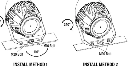
- Insert M20 and M10 bolts into the bracket. Tighten the bolts hand-tight to secure the luminaire while allowing for adjustment.
- Adjust the bracket and fixture vertically (and horizontally for Install Method 1) to the desired position.
- Fully tighten all bolts to secure the fixture.
Optional U-Bracket with Slip Fitter: For models using the optional U-Bracket (Item# 84080), secure the fixture in the bracket, place the slip fitter on the light pole, tighten bolts hand-tight, adjust to the desired angle, and fully tighten all bolts.
Wiring
The fixture requires standard electrical connections. Refer to the wiring diagram for specific wire assignments:
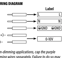
- Black: Line (L)
- White: Neutral (N)
- Green: Ground (GND)
- Purple: DIM (+)
- Gray: DIM (-)
Note for non-dimming applications: You must cap the purple and gray dimming wires separately. Failure to do so may cause malfunctioning and void the warranty.
Important notes
For the 1250W Stadium Light model, an external driver box is used. This driver box must be mounted within 85 feet of the fixture to prevent voltage loss.
Practical help
Common problems
Voltage loss on 1250W model
Ensure the external driver box is mounted within 85 feet of the fixture.
Malfunctioning in non-dimming applications
Cap the purple and gray dimming wires separately.
Before use
- Verify that the local voltage range corresponds with the working voltage of the fixture.
- Ensure power is disconnected at the circuit breaker before starting.
- Confirm the installer is a qualified electrician.
- Check that the mounting surface can support the fixture.
Specs in practice
- M20/M10 Bolts
- Mounting hardware used to secure the bracket to the surface.
Images and diagrams
- Install Method 1/2: Illustrates vertical and horizontal adjustment angles (110° and 240°).
- Wiring Diagram: Shows the color-coded connections for power and dimming control.
Model compatibility
- Optional U-Bracket (Item# 84080) is sold separately.
- 1250W model requires an external driver box.

Manual page author
Emily Carter
User documentation editor
Prepares concise manual descriptions and highlights the most useful setup, operation, and maintenance information for readers.