Lighting / Fixtures
Installation Instructions for Superior Life LED Linear High Bay
Quick installation guide for Superior Life LED Linear High Bay. Includes wiring diagrams for 120-277V connections, 0-10V dimming setup, and mounting options.
Table of contents
Manual images
Click an image to enlargeImportant Safety Information
Installation, service, and maintenance of these luminaires should be performed by a qualified licensed electrician. Always disconnect electrical power at the fuse or circuit breaker box before beginning any installation or maintenance work.
- Ensure supply voltage matches the luminaire label information.
- All wiring connections must be capped with UL approved wire connectors.
- Do not expose wiring to edges of sheet metal or other sharp objects to prevent damage.
- Suitable for Dry or Damp locations.
- Avoid direct eye exposure to the light source while it is on.
- Green ground screw is provided in the proper location and must not be relocated.
Installation
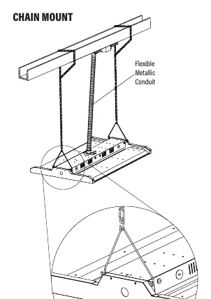
Standard Chain Mount:
- Remove the LED fixture from packaging and inspect for damages.
- Install the chain into the provided wire hanger.
- Secure the other end of the chain to a structure using hardware rated for the load.
- Install the wire hanger on the side of the top LED channel, ensuring the hangers are fully engaged into the side holes.
Wiring Instructions
Connect the LED high bay wiring to the line voltage wire:
- Black: Hot
- White: Neutral
- Green: Ground
0-10V Dimming: The driver compartment contains purple and pink (or gray) wires for 0-10V low voltage dimming. If you are not connecting the fixture to a 0-10V dimming circuit, ensure these dimmer leads are capped off separately from each other. Failure to do so may cause improper fixture operation and void the warranty.
Additional Mounting Options
The fixture supports alternative mounting methods, which are sold separately:
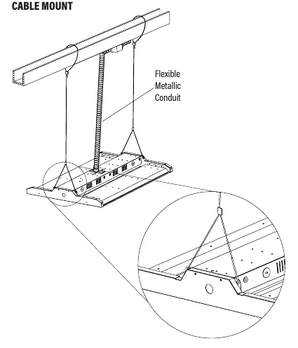
- Cable Mount: Allows for suspension using flexible metallic conduit.
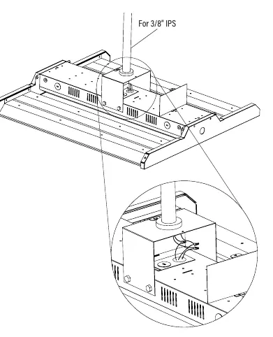
- Pendent Mount: Designed for use with 3/8 inch IPS.
Maintenance
Clean all residues and fingerprints from the new LED high bay and lens. Double-check all hanging hardware before finalizing the installation.
Practical help
Common problems
Improper fixture operation
Ensure 0-10V dimming leads (purple and pink/gray) are capped off separately if not connected to a dimming circuit.
Wiring damage or abrasion
Ensure wiring is not exposed to edges of sheet metal or other sharp objects during installation.
Before use
- Verify supply voltage matches the luminaire label.
- Ensure power is disconnected at the circuit breaker.
- Check that all hanging hardware is secure and rated for the load.
- Ensure 0-10V dimming leads are capped if not in use.
- Clean lens and fixture of fingerprints and residue.
Specs in practice
- 0-10V Dimming
- Low voltage control wires (Purple/Pink/Gray) used for dimming functionality.
Images and diagrams
- General Wiring Diagram: Illustrates connections for Line, Neutral, Ground, and the 0-10V dimming leads.
- Chain Mount: Shows how to attach the wire hanger to the top LED channel.
Model compatibility
- Suitable for Dry or Damp locations.
- 0-10V dimming requires an IEC compliant control.
- Cable and Pendent mounts are sold separately.

Manual page author
Emily Carter
User documentation editor
Prepares concise manual descriptions and highlights the most useful setup, operation, and maintenance information for readers.