Electronics / Speakers & Soundbars
Service Manual for Philips Hi-Fi MFB-Box 22RH545
Comprehensive service manual for the Philips Hi-Fi MFB-Box 22RH545. This document includes detailed adjustment procedures, disassembly instructions, technical theory, circuit diagrams, and service bulletins for maintenance and repair.
PDF source: NL · summary: English
Quick answers from the manual
Quick answer
- This document is a service manual for the Philips 22RH545 MFB-Box, providing technical specifications, adjustment procedures, disassembly instructions, and circuit diagrams for repair. p. 1, 4, 33
Key actions
- Adjustment procedure p. 4
- Disassembly p. 2, 3
Problems and fixes
Distorted sound
Perform adjustment procedure
p. 4Show 2 more answers Show less
Technical specifications
| Parameter | Value | Meaning | Pages |
|---|---|---|---|
| Mains voltage | 220V | Operating voltage | p. 1 |
Where to find it in the PDF
- Adjustment Procedures p. 4
- Schematics p. 9, 11, 12, 13
Table of contents
Manual images
Click an image to enlargeQuick guide from the manual
This service manual provides technical documentation for the Philips Hi-Fi MFB-Box 22RH545. It is intended for service technicians to perform repairs, adjustments, and maintenance. The document includes detailed schematics, PCB layouts, and service bulletins outlining component updates.
Adjustment Procedures
To ensure the device meets specifications, follow these adjustment steps:
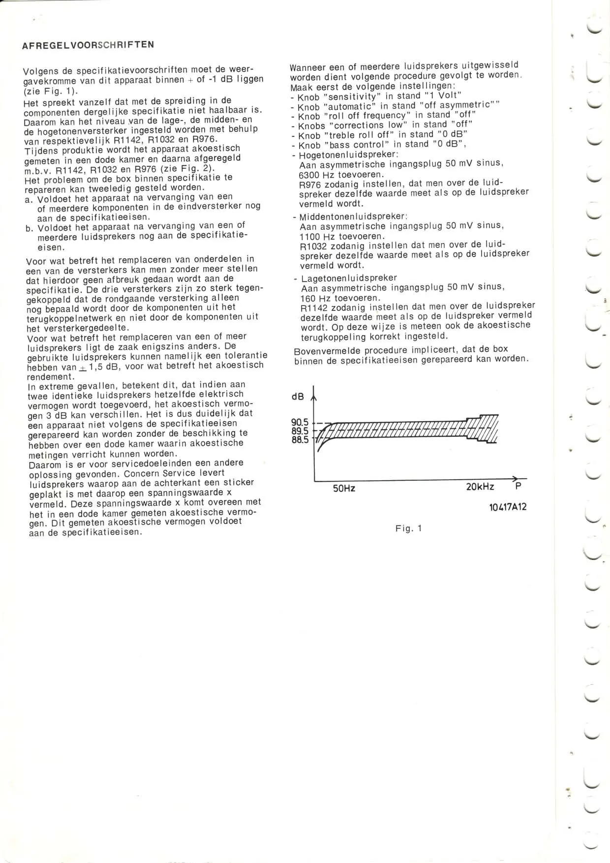
- Knob settings: Set 'sensitivity' to 1 Volt, 'automatic' to 'off asymmetric', 'roll off frequency' to 'off', 'corrections low' to 'off', 'treble roll off' to '0 dB', and 'bass control' to '0 dB'.
- Signal injection: Apply a 50mV sinus signal at 1100 Hz for the middle-tone speaker, 160 Hz for the low-tone speaker, and 6300 Hz for the high-tone speaker.
- Calibration: Adjust potentiometers R1142, R1032, and R976 to match the measured values on the speakers to the specified values.
Placement and Acoustic Filters
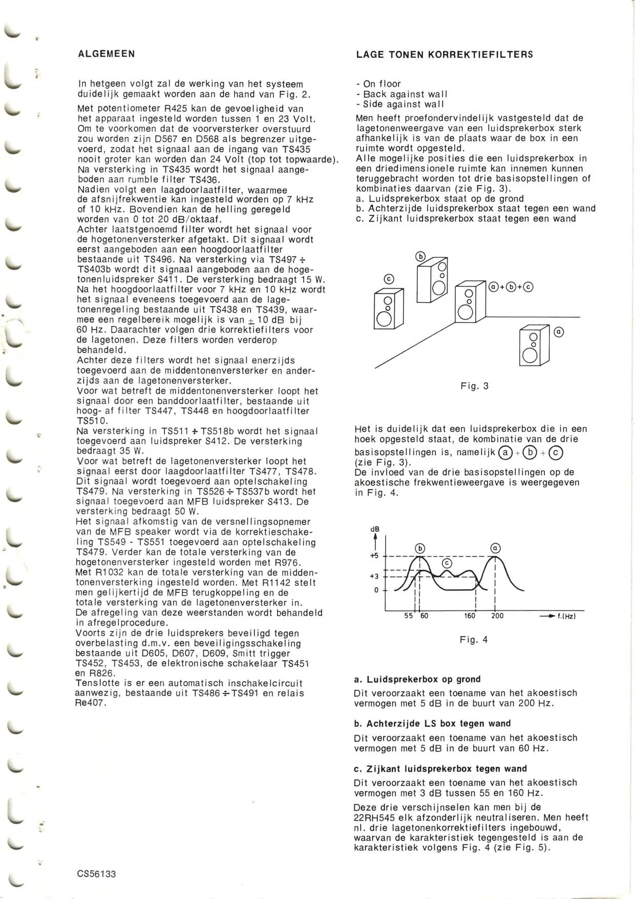
The acoustic performance of the MFB-Box is influenced by its placement in a room. The manual defines three basic positions:
- On floor: Increases acoustic power by 5 dB near 200 Hz.
- Back against wall: Increases acoustic power by 5 dB near 60 Hz.
- Side against wall: Increases acoustic power by 3 dB between 55 and 160 Hz.
These characteristics can be corrected using the built-in low-tone correction filters.
Disassembly and Repair
The manual provides visual guides for disassembling the unit:
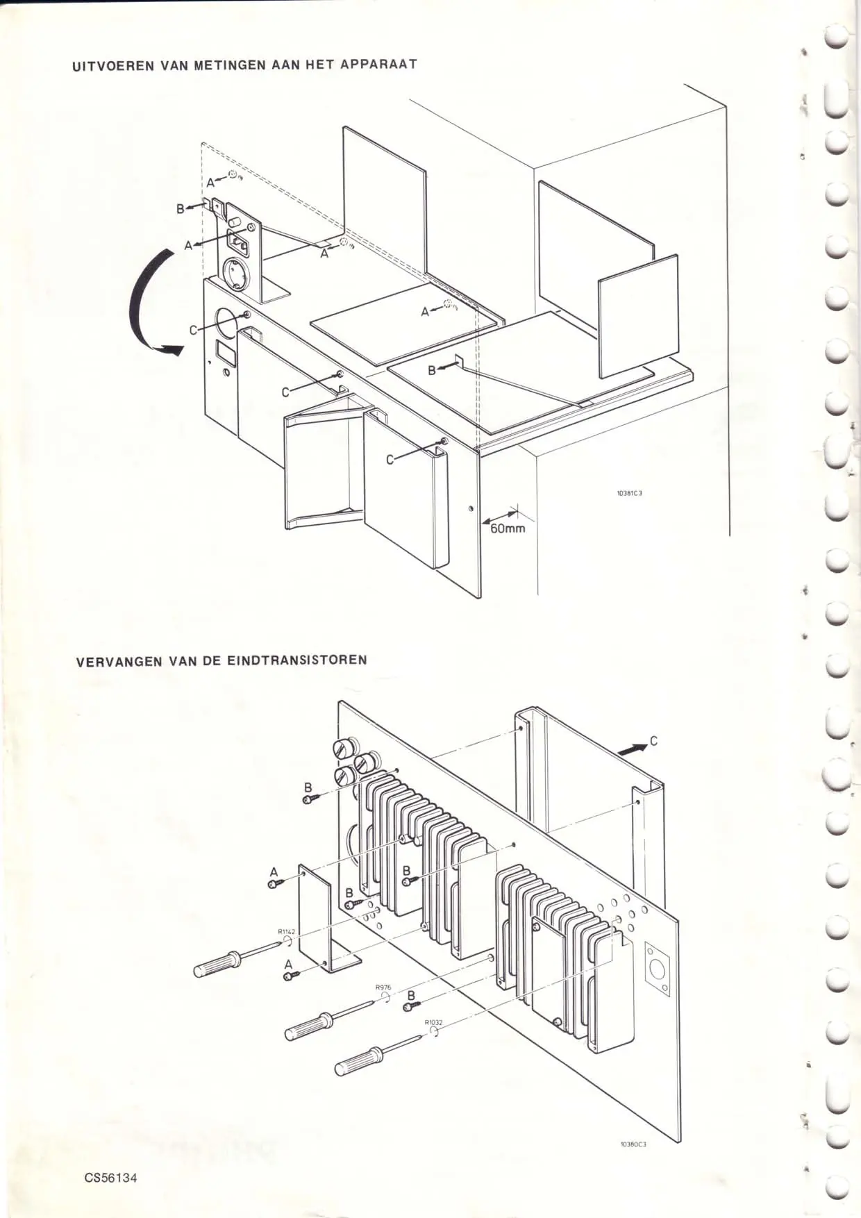
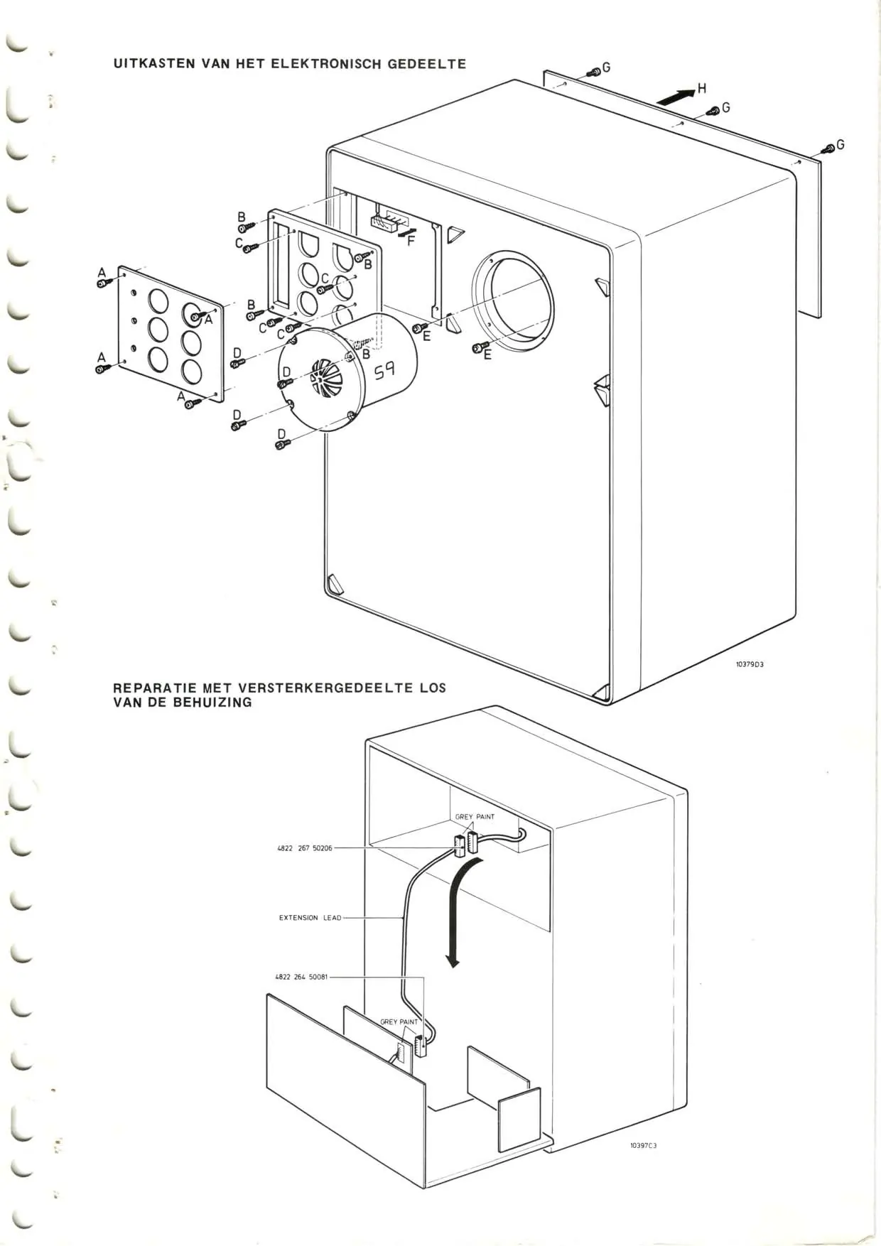
- Electronic section: Diagrams illustrate the removal of the electronic module and panels.
- Transistor replacement: Step-by-step visual instructions are provided for replacing the end transistors.
- Amplifier repair: Instructions for repairing the unit with the amplifier section removed from the housing.
Technical Theory
The manual details the design principles, including:
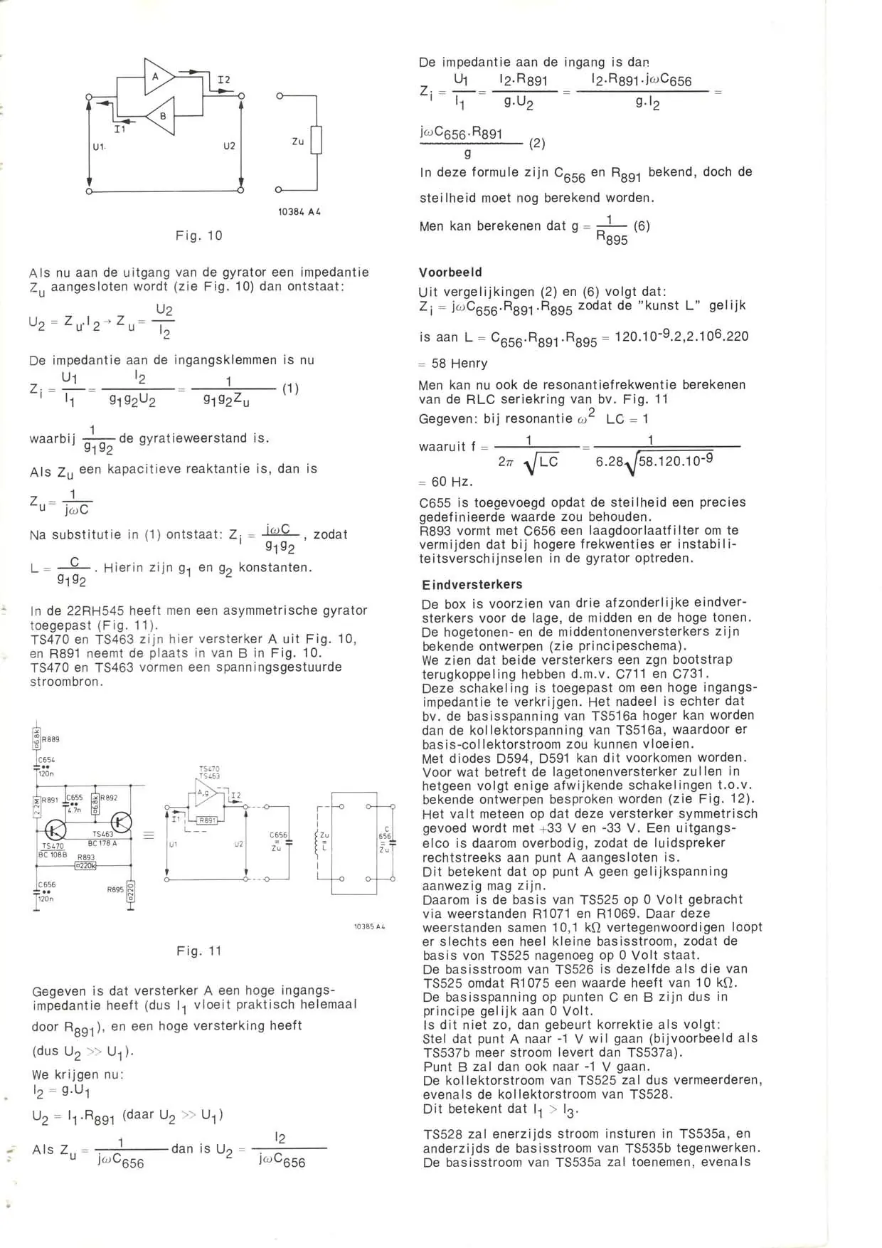
- Gyrator operation: Explains how the gyrator creates a constant current source and simulates inductance.
- Amplifier design: Describes the bootstrap feedback network used to achieve high input impedance.
- Protection circuits: Details the protection mechanisms for the speakers and the automatic switching circuit.
Service Bulletins
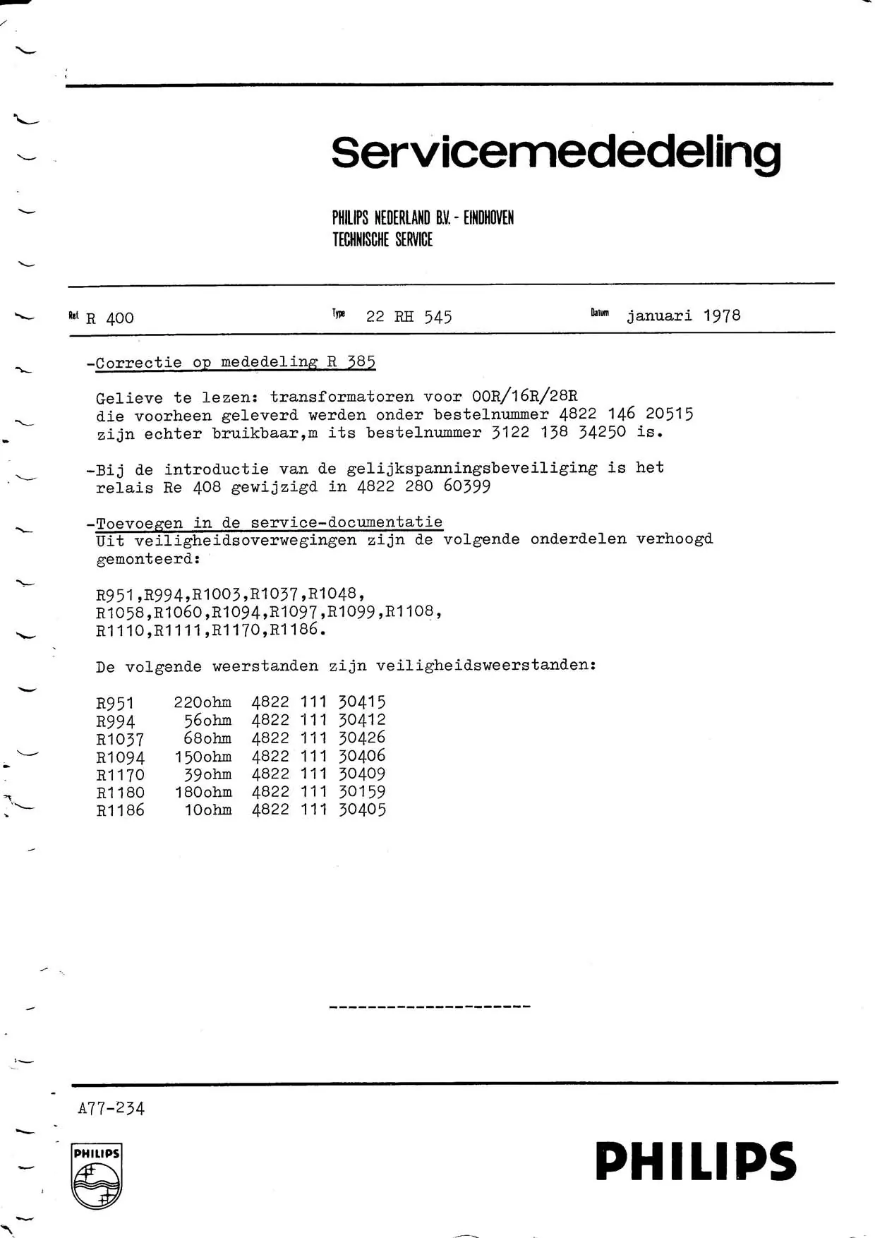
The document includes several service bulletins (R385, R400) that detail modifications to the original design, such as component value changes (e.g., R1185, R1180, R1173) and the addition of safety resistors.
Manufacturer information
Philips
Practical help
Common problems
Distorted sound or failure to meet specifications
Perform the adjustment procedure using 50mV sinus signals and the specified knob settings.
Need to replace transistors
Follow the disassembly diagrams on page 2 to access the amplifier section and replace the end transistors.
Before use
- Verify mains voltage (220V)
- Ensure correct placement (floor/wall) for optimal acoustic response
- Check knob settings (Sensitivity, Automatic, Roll-off, etc.) before testing
Show more Show less
Specs in practice
- Roll-off frequency
- Frequency at which the low-tone filter begins to attenuate
Images and diagrams
- Page 2: Disassembly of the electronic section and transistor replacement
- Page 3: Repair with amplifier section removed
- Page 5: Placement influence on acoustic response
- Page 34: Adjustment procedure schematic
Model compatibility
- The unit is designed for 220V mains voltage.
- Acoustic performance varies based on placement (floor, against wall, side against wall).

Manual page author
David Miller
Documentation analyst