Electronics / Speakers & Soundbars
Service Manual for Philips Hi-Fi M.F.B. Box 22RH541
Comprehensive service manual for the Philips Hi-Fi M.F.B. Box 22RH541. Includes detailed adjustment procedures for DC current and acoustic feedback, circuit diagrams, PCB layouts, parts lists, and technical service bulletins.
Quick answers from the manual
Quick answer
- This service manual provides technical instructions for the maintenance, adjustment, and repair of the Philips 22RH541 Hi-Fi M.F.B. Box, including circuit diagrams, PCB layouts, and parts lists. p. 1, 4, 11
Key actions
- Adjusting DC current p. 4
- Adjusting acoustic feedback p. 4
Problems and fixes
Incorrect DC current
Adjust R601 to 13.2 mV (40 mA).
p. 4Show 2 more answers Show less
Technical specifications
| Parameter | Value | Meaning | Pages |
|---|---|---|---|
| DC Current | 13.2 mV (40 mA) | Target voltage across R607 | p. 4 |
| Acoustic Feedback | 110-120 mV | Target voltage at S408 | p. 4 |
Where to find it in the PDF
- Introduction and Version Differences p. 1, 2
- Adjustment Procedures p. 4
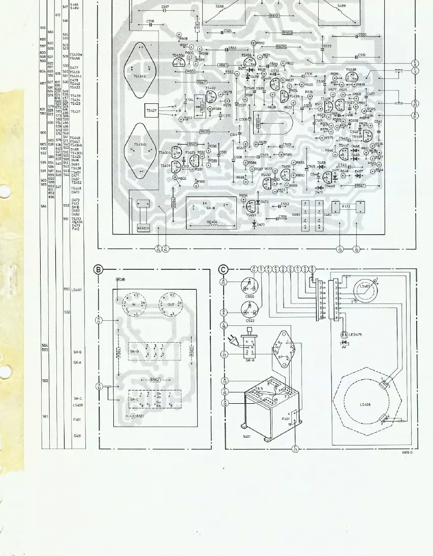
- Circuit Diagrams and PCB Layouts p. 5, 6, 7, 8
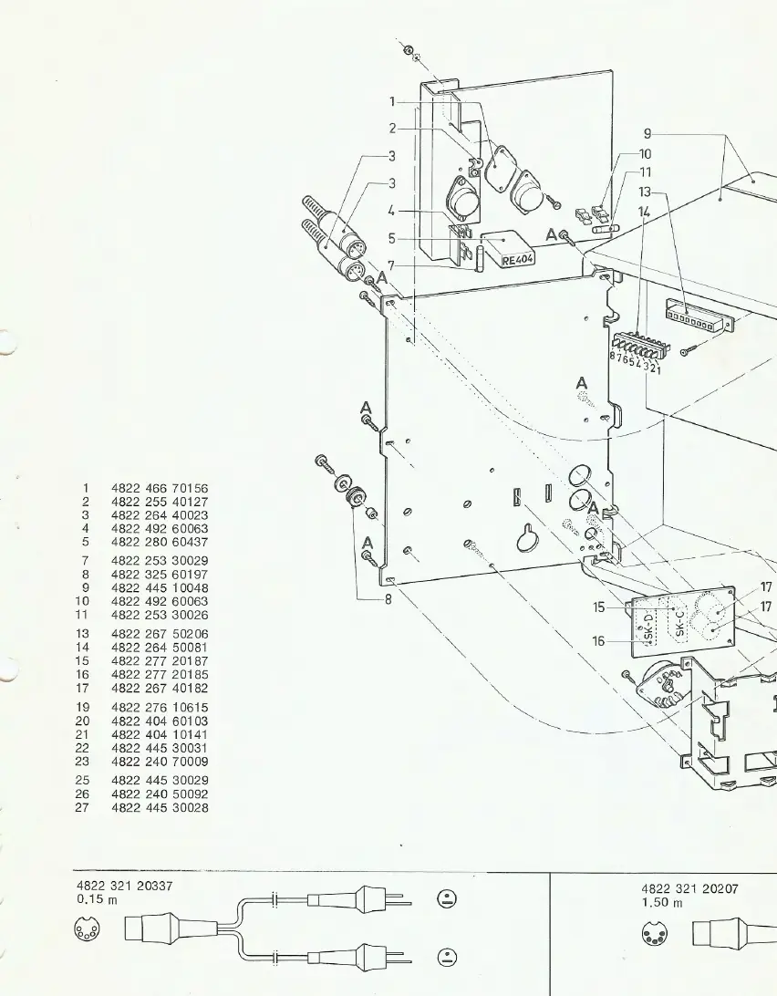
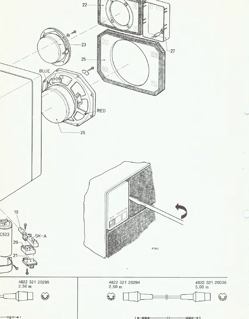
- Parts Lists and Exploded Views p. 9, 10, 11
- Service Bulletins p. 12, 13, 14
Table of contents
Manual images
Click an image to enlargeImportant Information from the Manual
This document is a technical service manual intended for qualified service personnel. It provides the necessary information to maintain, adjust, and repair the Philips 22RH541 Hi-Fi M.F.B. Box. It includes circuit diagrams, PCB layouts, parts lists, and specific service bulletins for component updates.
Adjustment Procedures
DC Current Adjustment
To adjust the DC current through the output stage:
- Connect a voltmeter across resistor R607.
- Adjust potentiometer R601 until the voltage reads 13.2 mV (40 mA).
Acoustic Feedback Adjustment
To adjust the acoustic feedback:
- Set switch SK-C to position 1 V - 10 kΩ.
- Apply a signal of 10 mV - 125 Hz to the input using a low-ohmic generator (≤ 100 Ω).
- Adjust potentiometer R630 until the voltage at S408 (points 5-6 of the plug) is 110-120 mV.
Technical Diagrams and Parts
The manual provides detailed schematics for the circuit boards and wiring. It also includes exploded view diagrams of the speaker assembly, which are essential for identifying parts during disassembly and reassembly. A comprehensive parts list is included, detailing transistors, diodes, capacitors, resistors, and miscellaneous components like transformers and fuses.
Service Bulletins
The manual contains technical updates (Service Mededeling) regarding component changes, such as updates to C512, C517, and R610, as well as information regarding tweeter replacements (AD 0162/T8 and AD 0140/T8) to ensure the unit is maintained to the latest specifications.
Manufacturer information
Philips
Practical help
Common problems
Incorrect DC current in output stage
Adjust R601 until the voltage across R607 is 13.2 mV (40 mA).
Acoustic feedback requires calibration
Adjust R630 until the voltage at S408 (points 5-6) is 110-120 mV with a 10 mV - 125 Hz input signal.
Before use
- Verify the mains voltage setting (110V, 127V, 220V, or 240V) matches the local power supply.
- Ensure all signal cables are connected correctly.
- Check for proper grounding of the unit.
- Verify that the speaker driver and components match the latest service bulletin specifications.
Show more Show less
Specs in practice
- Acoustic Feedback
- A control loop parameter adjusted via R630 to ensure accurate speaker response.
Model compatibility
- The unit supports multiple mains voltages (110V, 127V, 220V, 240V) via internal switching.
- Component values may have been updated in later production runs; refer to the service bulletins at the end of the manual.

Manual page author
Michael Turner
Technical manual editor