Electronics / PA Systems
Instruction Manual for Taga Harmony TCA Series 100V Multizone Mono Mixing Amplifier
Quick guide for Taga Harmony TCA Series 100V Multizone Mono Mixing Amplifiers. Learn about installation, speaker connections, operation, and safety precautions.
Table of contents
Manual images
Click an image to enlargeQuick guide from the manual
The Taga Harmony TCA Series amplifiers are designed for commercial installations such as restaurants, shops, and conference rooms. They support 100V/70V and low-impedance speaker systems. Key operational requirements include ensuring proper ventilation, correct speaker impedance matching, and avoiding simultaneous connection of different speaker types (100V/70V and low-impedance).
Safety Instructions
- Indoor Use Only: This amplifier is intended for indoor environments.
- Ventilation: Do not block cooling slots. Ensure at least 5cm of free space around the unit.
- Electrical Safety: Do not open the cover. Refer servicing to qualified personnel.
- Connection Safety: Always switch off the amplifier before connecting speakers to avoid damage.
- Environment: Keep away from moisture, heat sources, and liquids.
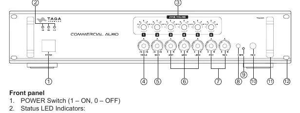
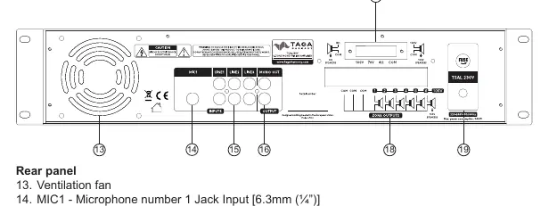
Front and Rear Panel
The front panel features the Power switch, status LEDs (ON, SIG, CLP), Zone Volume regulators, Treble/Bass controls, Line input mixing regulators, Microphone mixing regulators, and the Chime button. The rear panel contains the ventilation fan, MIC1 input, LINE inputs (RCA), MONO OUT, and screw-in speaker connectors for Zone Outputs and Additional Speaker Output.
Rack Installation
The amplifier is designed for 19-inch rack mounting and requires 2 rack spaces (89mm). Secure the unit using the four mounting holes. It is recommended to use additional lateral rails or a bottom plate for stability. Ensure hot air is dissipated to prevent overheating.
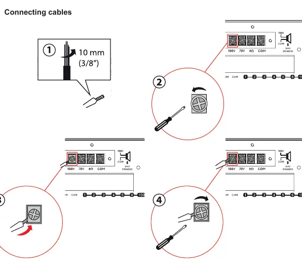
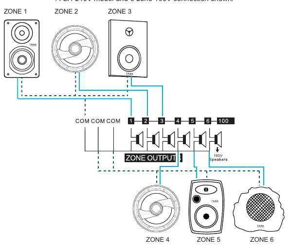
Speaker Connection
The amplifier supports two main connection options: Additional Speaker Output (for a single zone) and Zone Outputs (for multiple zones). Warning: Never connect both options simultaneously. Use 10AWG cables for runs longer than 20 meters. Ensure correct polarity (COM to negative/black, 100V/70V/Ω to positive/red).
Hooking up the Amplifier
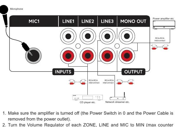
- Ensure the amplifier is turned off and the power cable is disconnected.
- Set all volume regulators (ZONE, LINE, MIC) to MIN (counter-clockwise).
- Connect speakers to the appropriate terminals (100V, 70V, or low-impedance).
- Connect audio sources (CD player, network streamer) to the LINE inputs using RCA cables.
- Connect external devices (e.g., power amplifier) to the MONO OUT if needed.
- Connect microphones to the MIC inputs.
Operation
- Powering On: Press the Power Switch. The ON LED should light up.
- Volume Control: Adjust ZONE VOLUME for each zone. LINE and MIC regulators control the mixing levels.
- Microphone Priority: The MIC2 input has priority over other active inputs; when used, other inputs are muted.
- Chime: Press the CHIME button to mute LINE inputs and broadcast a chime before an announcement.
- Indicators: The SIG LED flashes when an audio signal is received. The CLP LED indicates signal overload; reduce volume if it flashes.
Cleaning and Maintenance
Do not use strong or abrasive cleaners. Use a damp, soft cloth for cleaning. If a fuse blows, replace it only with the exact same type as indicated on the rear panel.
Practical help
Common problems
No sound / Power LED off
Check power cable connection. If the amplifier does not turn on, check for short-circuited speaker cables.
Clipping LED (CLP) flashing
The signal is overloaded. Turn down the volume or line input levels.
Distortion or poor sound quality
Ensure volume knobs are not at the maximum position. Reduce volume levels.
Before use
- Ensure the amplifier is switched off before making any connections.
- Verify speaker impedance compatibility (100V/70V or low-impedance).
- Do not connect 100V/70V and low-impedance speakers simultaneously.
- Ensure proper ventilation; do not block cooling slots.
- Use appropriate gauge speaker cables (10AWG recommended for runs >20m).
- Set all volume knobs to minimum before initial power-up.
Specs in practice
- Zone Outputs
- Allows independent volume control for multiple speaker zones.
Images and diagrams
- Front Panel: Identifies power switch, status LEDs, and volume/mixing controls.
- Rear Panel: Shows input/output ports, speaker terminals, and ventilation fan.
- Speaker Connection: Illustrates wiring for 100V/70V vs low-impedance modes.
Model compatibility
- Never mix 100V/70V and low-impedance speakers on the same output.
- 70V connection is not available for the ZONE OUTPUTS.

Manual page author
Emily Carter
User documentation editor
Prepares concise manual descriptions and highlights the most useful setup, operation, and maintenance information for readers.