Power / Solar Inverters
User Manual for PowMr POW-SunSmart 8K/10K Solar Charge Inverter
Quick guide and user manual for the PowMr POW-SunSmart 8K and 10K solar charge inverters. Includes installation, wiring diagrams, settings, troubleshooting, and maintenance instructions.
Table of contents
Manual images
Click an image to enlargeImportant Information from the Manual
The PowMr POW-SunSmart 8K and 10K are all-in-one solar charge inverters designed for indoor use (IP20). Installation and wiring must be performed by a certified technician in compliance with local electrical codes. Do not parallel this device with other AC input sources. Ensure all connections are tight and the unit is well-ventilated. The open circuit voltage of the PV array must not exceed 500V.
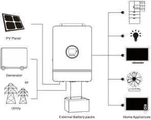
System Connection Diagram
A complete system includes PV modules, utility grid or generator, battery, home load, and the inverter. The inverter acts as the central energy conversion device. Wiring methods vary based on the application (split-phase or single-phase).
Installation
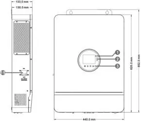
Choose a solid wall for mounting at eye level. Ensure adequate heat dissipation space (at least 200mm on sides). The ambient temperature should be between -10°C and 55°C. Use an electric drill to make mounting holes and secure the unit with M5 screws.

Connection
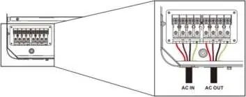
AC Input & Output: Connect live, neutral, and ground wires according to the terminal labels. Ensure circuit breakers are open before connecting to avoid electric shock.
Battery Connection: Connect positive and negative cables. Ensure correct polarity to avoid damage. Use appropriate cable diameters (34mm²/2 AWG for 8KW, 42mm²/1 AWG for 10KW).
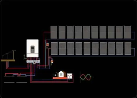
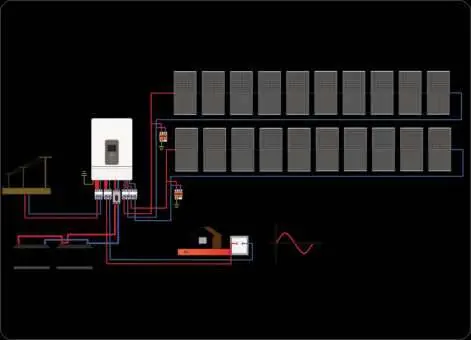
PV Connection: Connect two strings of PV according to the diagram. Ensure the open circuit voltage does not exceed 500V.
Grounding: Connect the grounding terminal to the grounding busbar using a cable of at least 4mm².
Operation
The display panel features an LCD screen, 3 LED indicators, and 4 touchable keys. Use the keys to navigate the menu and adjust parameters. The system supports various output modes (Utility Priority, Solar Priority, Inverter Priority) and charging modes (Hybrid, Only Solar).
Communication
The inverter supports USB, RS485, and CAN communication. A Wi-Fi/GPRS module can be purchased separately for remote monitoring via the mobile app.
Troubleshooting
The inverter displays fault codes on the LCD screen. Common issues include battery under-voltage, overload, and communication errors. Refer to the fault code table in the manual for specific remedies, such as checking battery connections, reducing load, or restarting the device.
Maintenance
Check the system twice a year. Ensure airflow is not blocked, inspect conductors for damage, verify display consistency, check terminals for corrosion, and clean the insect screen regularly.
Practical help
Common problems
No screen display
Check if the battery or PV air-switch is closed, the bottom switch is ON, and press any button to wake the screen.
Battery under-voltage
Charge the battery until the voltage exceeds the threshold set in parameter 14.
Disconnected battery
Check battery connections, ensure the circuit breaker is closed, and verify BMS communication.
Inverter overload
Reduce the load power and restart the device.
Before use
- Ensure installation is performed by a certified technician.
- Verify PV open circuit voltage is below 500V.
- Check that all electrical connections are tight and secured.
- Ensure adequate ventilation space around the inverter.
- Confirm battery type and settings match the connected battery.
Specs in practice
- Rated Output Power
- 8,000W for 8K model; 10,000W for 10K model.
- Max. PV Input Current
- 22A per circuit.
- Max. Voltage of Open Circuit
- 500Vdc.
- Protection Level
- IP20, for indoor use only.
Images and diagrams
- System Connection Diagram: Illustrates the integration of PV, battery, grid, and loads.
- Display Panel: Shows icons for PV, battery, inverter, and load status.
- Wiring Diagrams: Provides visual guides for split-phase and single-phase configurations.
Model compatibility
- Supports lead-acid and Li-ion batteries.
- Requires Wi-Fi/GPRS module (purchased separately) for app monitoring.
- Compatible with split-phase and single-phase output modes.

Manual page author
Emily Carter
User documentation editor
Prepares concise manual descriptions and highlights the most useful setup, operation, and maintenance information for readers.