Automotive / Car Audio
User Guide for Pyle Hydra 2-Channel Amplifier
Quick guide for the Pyle Hydra 2-Channel Amplifier. Includes installation precautions, wiring diagrams, control settings, and Bluetooth connection instructions for models PLMRMP1A, PLMRMP1B, PLMRMB2CW, PLMRMB2CB, PLMRKT2A, and PLMRKT2B.
Quick answers from the manual
Quick answer
- The Pyle Hydra 2-Channel Amplifier is designed for marine audio systems. Installation requires connecting the battery (12V DC), remote turn-on, and speakers according to the color-coded wiring guide. Input levels and polarity should be adjusted based on your audio source. p. 5, 6, 7
Key actions
- Adjusting Input Level p. 6
- Connecting Bluetooth p. 6
First start
- Disconnect battery, connect power and speaker wires, then adjust gain and input levels. p. 5, 6, 7
Problems and fixes
Input overload/distortion
Do not misuse the level control as a volume knob; adjust it to match the source output level.
p. 5Maintenance and reset
- Replace power fuse only with an identical type/rating. p. 5
Where to find it in the PDF
- Installation Precautions p. 4
- Controls and Settings p. 5, 6
- Wiring Diagram p. 7
Table of contents
Manual images
Click an image to enlargeQuick Guide
This manual provides instructions for the Pyle Hydra 2-Channel Amplifier series. Key operations include proper wiring, adjusting input levels, and configuring Bluetooth for compatible models. Always disconnect the marine vessel battery before performing any wiring.
Installation Precautions

- Vessel Layout: Carefully investigate the vessel's layout before drilling or cutting any holes.
- Critical Components: Exercise caution when working near gas tanks, fuel lines, hydraulic lines, and existing electrical wiring.
- Mounting: Never operate the amplifier when it is unmounted. Ensure all audio system components are securely attached to prevent damage.
- Wire Protection: Do not mount the amplifier in a way that leaves wire connections unprotected, pinched, or in contact with metal surfaces.
Controls and Settings
The amplifier features several controls to optimize audio performance:
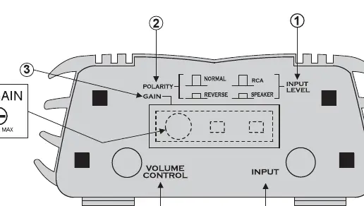
- INPUT LEVEL Switch: Set to LINE (out) for RCA sources or SPEAKER (in) for high-level sources/loudspeaker outputs. Ensure the watertight plug is replaced after adjustment.
- POLARITY Switch: Optimizes bass performance. Switch between NORMAL and REVERSE while playing bass-heavy music to find the best response. Leave in NORMAL if unsure.
- GAIN Control: Adjusts the overall amplifier level. Set as low as possible while maintaining full output power. If using an external volume control, set to FULL (clockwise) and adjust the amplifier gain accordingly.
Power and Speaker Wiring
Follow these color codes for proper installation:
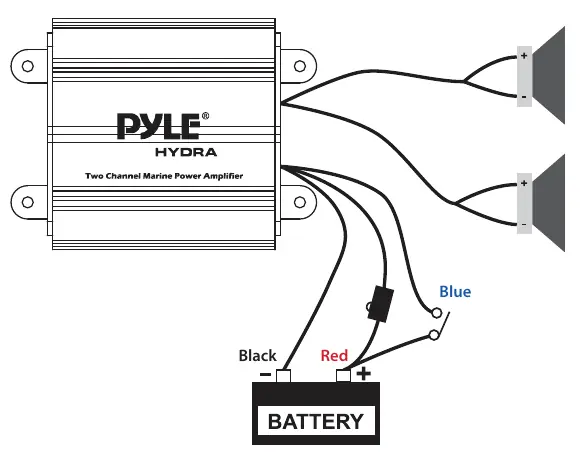
- Red: Battery (+), 12V DC
- Black: Battery (-), Ground
- Blue: Remote Turn On, 12V DC = ON
- White: CH1 (+)
- White/Black: CH1 (-)
- Gray: CH2 (+)
- Gray/Black: CH2 (-)
Bluetooth Connection
Note: Only models PLMRMB2CW and PLMRMB2CB feature built-in Bluetooth.
- Turn on the amplifier; the red Bluetooth indicator LED will blink.
- Open the Bluetooth settings on your phone.
- Search for and connect to the device named pyle amplifier.
- The red LED will remain solid once the connection is successful.
Practical help
Common problems
Audio distortion or protection circuit engaging
The input level control may be set too high. Adjust it to match the output level of your audio source, not as a volume control.
Bluetooth not connecting
Ensure you are using a compatible model (PLMRMB2CW or PLMRMB2CB). Verify the red Bluetooth LED is blinking before attempting to pair.
Before use
- Disconnect the marine vessel battery before making power connections.
- Ensure the head unit is turned off while connecting input jacks and speaker terminals.
- Verify the mounting location is free of fuel lines and electrical wiring.
- Use only an identical fuse if replacement is necessary.
- Ensure all wire connections are protected and not pinched.
Specs in practice
- INPUT LEVEL Switch
- Determines input sensitivity. Use LINE for RCA sources, SPEAKER for high-level sources.
- POLARITY Switch
- Optimizes bass performance when multiple sets of speakers are used.
- GAIN Control
- Matches the amplifier's sensitivity to the source's output level.
Images and diagrams
- The control panel diagram identifies the Input Level switch, Polarity switch, Gain control, Volume Control plug, and Input jacks.
- The wiring diagram illustrates the connection points for the battery (Red/Black), Remote Turn On (Blue), and speaker channels (White/Gray).
Model compatibility
- Bluetooth functionality is exclusive to models PLMRMB2CW and PLMRMB2CB.

Manual page author
David Miller
Documentation analyst
Organizes user manual content into clear summaries, with attention to model details, product context, and everyday usability.